4. Load limiter working principles
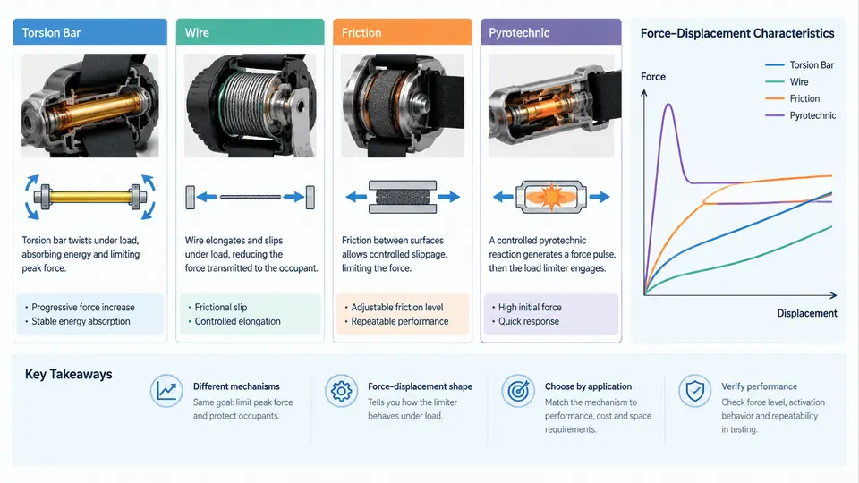
A load limiter is the element that decides how much belt force the occupant is allowed to "feel" during a crash. Its job is not to absorb energy in the abstract, but to cap the force transmitted through the webbing at a level the human chest can tolerate, while still allowing the occupant to ride down into the restraint system. Every load limiter is therefore a force-displacement device: the design target is a controlled plateau of belt force over a defined payout of webbing. The four mainstream mechanisms — torsion bar, wire, friction, and pyrotechnic — reach that plateau through very different physical processes, and their force-displacement curves differ in shape, stability, and controllability.
Force-displacement as the common language
Before comparing mechanisms, fix the reference convention used throughout this chapter. Belt force F is measured along the webbing at the retractor or buckle anchor, positive in tension. Displacement x is the length of webbing paid out from the retractor after the pretensioner has fired and the lock has engaged, positive in the payout direction. A load limiter is characterized by three numbers: the plateau force Fp, the total payout xmax, and the energy absorbed, which is the area under the F–x curve. A good limiter holds Fp nearly constant; a poor one spikes, sags, or oscillates, and the occupant experiences that variation directly.
Torsion bar: the baseline
The torsion bar limiter is the most common design. A hardened steel bar is fixed at one end to the retractor frame and at the other to the spool. When the belt locks and the occupant loads the webbing, the spool rotates and twists the bar. The bar yields plastically and, in doing so, converts belt work into plastic deformation of steel. The plateau force is set by the bar's torsional yield strength and geometry:
F_p ≈ (π · d³ · τ_y) / (16 · R_spool)

d       = bar diameter (mm)
τ_y     = torsional yield strength of bar material (MPa)
R_spool = effective spool radius (mm)
For a representative example, a bar of d = 6.0 mm, τy = 1200 MPa, and Rspool = 22 mm gives Fp ≈ 4.6 kN. The characteristic curve is a steep rise to the plateau, then a nearly flat, slightly rising trace as the bar work-hardens. The total payout is limited by how many turns the bar can twist before fracture, typically 1.5–3 turns, corresponding to 200–400 mm of webbing. The torsion bar is cheap, passive, and highly repeatable, but its plateau is fixed at build time — it cannot adapt to occupant mass or crash severity.
Wire limiter: drawing energy through a die
A wire limiter replaces the twisting bar with a steel wire pulled through a calibrated bending die or around a set of pins. As webbing pays out, the wire is drawn through the die and plastically bent and unbent, absorbing energy. The plateau force is governed by wire diameter, die radius, and the number of bends:
F_p ≈ n · (σ_y · A_wire · t) / (2 · R_die)

n      = number of bend passes
A_wire = wire cross-section area (mm²)
R_die  = die bend radius (mm)
t      = wire thickness factor (≈ 1 for round wire)
The wire limiter produces a very stable, flat plateau and can be tuned over a wider force range than a torsion bar by changing wire gauge or die geometry. Its weakness is packaging: the wire must be long enough to provide the required payout, and the die must be precisely aligned to avoid force spikes at the entry and exit of each bend.
Friction limiter: force from sliding contact
A friction limiter clamps the webbing or a metal strap between friction pads and lets it slide under a calibrated normal force. The plateau force is set by the friction coefficient and clamp load:
F_p = μ · N · (effective contact factor)

μ = pad-to-webbing friction coefficient
N = clamp normal force (N)
Friction limiters are compact and can be designed with a progressive clamp that increases force with payout. Their characteristic curve, however, shows a sawtooth ripple caused by stick-slip: the strap alternately sticks and releases, producing force oscillations of 5–15% around the mean. This ripple is acceptable in many applications but must be filtered when validating chest deflection, because the occupant's chest responds to the peak, not the mean.
Pyrotechnic limiter: force that changes mid-crash
A pyrotechnic (adaptive) limiter uses a small gas generator or a pyrotechnically released clamp to change the force level during the crash. In the common two-stage design, the belt first pays out at a high plateau; after a calibrated delay or payout distance, the pyrotechnic element fires and either releases a second torsion bar or reduces the clamp force, dropping the belt to a lower plateau. The curve is therefore a stepped trace: a high-force first stage for a heavy occupant or a severe crash, then a lower-force second stage to limit chest loading. The design variables are the stage-1 force, the switch point (time or payout), and the stage-2 force. The switch point must be chosen so that the occupant has already been decelerated enough that the lower force does not allow excessive forward excursion.
Comparing the four mechanisms
| Mechanism | Plateau shape | Typical Fp range | Payout | Adaptivity | Key risk |
|---|---|---|---|---|---|
| Torsion bar | Flat, slightly rising | 3–6 kN | 200–400 mm | None (passive) | Bar fracture at high payout |
| Wire | Very flat | 2–7 kN | 150–350 mm | Limited (gauge/die) | Die misalignment spikes |
| Friction | Sawtooth ripple | 2–5 kN | 100–250 mm | Progressive clamp possible | Stick-slip, pad wear |
| Pyrotechnic | Stepped, two-stage | 3–7 kN stage 1; 2–4 kN stage 2 | 250–450 mm | High (event-triggered) | Switch-point calibration |
Reading the curve in practice
When validating a limiter on a sled or component rig, plot belt force against payout and check four things. First, the plateau force should sit within ±10% of the target over the middle 70% of payout; excursions outside that band indicate bar yield inconsistency, die wear, or pad contamination. Second, the initial rise should be steep — a slow rise means the limiter is engaging late and the occupant has already loaded the belt. Third, the total payout must reach the design value before the limiter bottoms out; a short payout produces a sharp force spike at the end of travel, which is the most common cause of excessive chest deflection in an otherwise well-tuned system. Fourth, for pyrotechnic limiters, verify the switch point against the intended trigger: a switch that fires too early drops force before the occupant has been decelerated, and a switch that fires too late leaves the chest exposed to the high stage-1 force for too long.
The four mechanisms are not interchangeable drop-in parts. The torsion bar and wire limiter are passive, repeatable, and cheap, and suit high-volume platforms with a single occupant population. The friction limiter trades curve quality for compactness and progressive force. The pyrotechnic limiter is the only one that can change force mid-event, and it is therefore the natural choice when the same restraint must serve a wide occupant mass range or when crash severity sensing is available. The next design question — how to size the plateau and payout for a given occupant and crash pulse — builds directly on the force-displacement behavior described here.