1. System architecture of seatbelt restrain
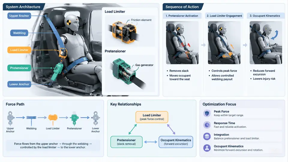
A modern three-point seatbelt is not a passive strap. It is a small, tightly coordinated restraint system whose behavior is decided in the first 100–150 ms of a crash. Two devices dominate that behavior: the pretensioner, which removes slack and couples the occupant to the vehicle early, and the load limiter, which then controls how much force the belt is allowed to feed into the occupant's chest. Understanding how these two devices are integrated — mechanically, electrically, and in terms of force path — is the prerequisite for any performance optimization work later in this course.
1.1 The restraint chain as a force path
Every belt force follows a closed loop. During a frontal impact the occupant moves forward relative to the vehicle; the belt converts that relative motion into a force path that runs from the occupant's body, through the webbing, into the retractor and buckle anchorages, and finally into the vehicle body structure. The path can be decomposed into four segments:
- Occupant interface — the diagonal shoulder section and the lap section distribute force over the chest, clavicle, and pelvis. Geometry here determines pressure distribution and the risk of submarining.
- Webbing and slip — the belt is not rigid; webbing elongation and slip through the D-ring and tongue change the effective stiffness seen by the occupant.
- Energy-management element — the load limiter, usually a torsion bar inside the retractor spool, or a profiled deformation element in the buckle pretensioner. This is where force is deliberately capped.
- Anchorage and body structure — retractor mounting, buckle stalk, and anchor plate transfer the remaining load into the sill, B-pillar, and floor. Structural compliance here adds to the total ride-down distance.
The key architectural insight is that these segments are in series. The force that reaches the occupant is limited by the softest element in the chain, and the total forward displacement of the occupant is the sum of the deformation of every segment. A load limiter that pays out 120 mm of webbing is only useful if the anchorage and structure do not add uncontrolled compliance on top of it.
1.2 Pretensioner types and their integration points
Pretensioners are integrated at two typical locations, and the choice affects the whole architecture:
| Type | Location | Typical pull-in | Integration consequence |
|---|---|---|---|
| Retractor pretensioner | Inside retractor frame | 60–120 mm webbing | Acts on shoulder belt; must share the spool with the torsion-bar load limiter |
| Buckle pretensioner | Buckle stalk / anchor | 40–80 mm | Pulls the tongue down; reduces lap belt slack directly, complements shoulder pull-in |
| Dual pretensioner | Both locations | Combined | Best slack removal, but requires coordinated firing and careful force-path design |
Pyrotechnic pretensioners are triggered by the airbag control unit (ACU) via a firing loop; motorized retractor pretensioners are driven by a reversible electric motor and can also serve comfort functions such as belt slack reduction before impact. In either case, the pretensioner must be mechanically decoupled from the load limiter's force-limiting function: the pull-in happens first, then the torsion bar begins to twist and pay out webbing. If the two functions are not properly sequenced, the pretensioner can fight the load limiter and produce a force spike.
1.3 How the load limiter is integrated
The most common load limiter is a torsion bar inside the retractor spool. When belt force exceeds a threshold, the spool rotates against the twisting bar and pays out webbing at a roughly constant force. The force level is set by bar diameter, material, and effective length; typical passenger-car values are 3–6 kN at the shoulder, with adaptive systems switching between two levels (for example 4 kN and 6 kN) using a second bar or a pyrotechnic switch.
Integration matters in three places. First, the torsion bar and the pretensioner share the same spool, so the pretensioner's pull-in must be completed before the bar starts to yield; otherwise the pretensioner stroke is wasted. Second, the load limiter's payout adds to the occupant's forward excursion, so it must be matched to the available ride-down distance between the occupant and the airbag, steering wheel, or dashboard. Third, the force level must be tuned together with the airbag's venting and the seat's energy absorption — a soft load limiter with a stiff airbag simply moves the injury risk from the chest to the head and neck.
1.4 Occupant kinematics and the coupling to architecture
The architecture exists to shape occupant kinematics. In a frontal impact the sequence is roughly: pretensioner fires (10–20 ms), occupant begins to load the belt (20–40 ms), load limiter yields and pays out webbing (40–90 ms), airbag contacts the head and chest (50–80 ms), and the occupant rides down the remaining energy (90–150 ms). The load limiter's force level and payout determine how far the chest travels; the pretensioner determines how early that travel starts from a coupled position rather than a slack one.
Two failure modes are directly architectural. Submarining occurs when the lap belt does not engage the pelvis and the occupant slides under it — often caused by a lap belt routed too high, insufficient buckle pretension, or a load limiter that pays out so much webbing that the lap geometry changes. Out-of-position loading occurs when the pretensioner pulls an occupant who is already close to the airbag, increasing the risk of airbag-induced injury; this is why occupancy sensing and firing suppression are part of the system architecture, not an afterthought.
1.5 Reading the architecture as a design problem
With the force path and timing in view, the integration problem becomes concrete. The pretensioner must fire early enough to remove slack before the occupant loads the belt, but not so early that it pulls an out-of-position occupant into the airbag. The load limiter must be soft enough to keep chest deflection within injury criteria, but stiff enough that the occupant does not bottom out the airbag or strike the steering wheel. The anchorages and structure must be stiff enough to make the load limiter the dominant compliance, yet compliant enough to contribute controlled ride-down.
A practical way to evaluate a proposed architecture is to build a one-dimensional lumped-parameter model: occupant mass on a spring representing the belt, a force-capped element representing the load limiter, and a parallel spring representing structure. Running a 50 km/h frontal pulse through this model gives the chest acceleration and forward excursion before any hardware exists. The model is deliberately simple, but it exposes the two numbers that matter most in concept phase — peak chest acceleration and total excursion — and shows immediately whether the pretensioner stroke and load-limiter payout are balanced against the available package space.
The next step in this course is to quantify each element: pretensioner pull-in force and stroke, torsion-bar force level and payout curve, and the structural compliance that sits behind them. The architecture described here is the frame those numbers must fit into.