1. Course overview
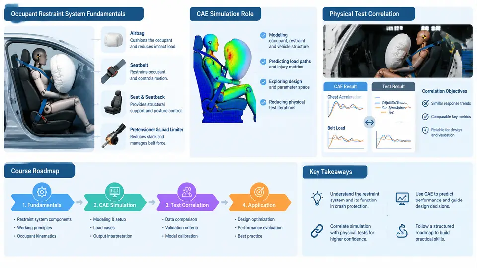
Occupant restraint development sits at the intersection of crash mechanics, structural design, and regulatory compliance. A modern vehicle must protect occupants across a wide range of impact scenarios — frontal, oblique, side, and rear — while satisfying legal requirements such as FMVSS 208, ECE R94/R95, and consumer rating programs like Euro NCAP and C-NCAP. The restraint system is the last line of defense in that chain, and its performance is judged by measurable injury criteria: HIC36/HIC15 for the head, Nij and chest deflection for the thorax, femur loads, and neck injury metrics. This course teaches how those systems are engineered in CAE and how simulation results are made to agree with physical sled and vehicle crash tests.
What the Restraint System Actually Does
A restraint system is not a single component but a coordinated energy-management chain. The seat belt retractor, webbing, buckle, and anchor points control occupant kinematics in the early phase of a crash. The pretensioner removes slack within the first 10–20 ms, and the load limiter then caps belt force — typically in the 3–6 kN range for a front occupant — to trade chest deflection against forward excursion. The airbag module, inflator, and venting strategy handle the later phase, cushioning the head and distributing load across the face and chest. The seat structure, cushion stiffness, and anti-submarining pan determine how the occupant is positioned before any of these devices act.
These elements interact, and that interaction is what makes restraint design difficult. A stiffer load limiter reduces excursion but raises chest deflection. An earlier pretensioner trigger improves coupling but can increase neck load if the occupant is out of position. A larger airbag volume reduces head acceleration but changes the timing of head contact relative to belt loading. CAE exists precisely because these trade-offs cannot be resolved by intuition or by testing every combination physically.
The Role of CAE Simulation
In restraint CAE, the occupant is represented by a validated finite element or multibody dummy model — the Hybrid III 50th percentile male is the baseline, with 5th percentile female and 95th percentile male variants for coverage. The dummy is positioned in a full vehicle interior model or a sled buck, restrained by belt elements, and loaded by an airbag model using either uniform pressure or corpuscular particle methods (CPM). The solver — typically LS-DYNA for explicit crash — advances the model in time steps on the order of 1 µs, resolving belt slip through slip rings, retractor spool-out, airbag inflation, and contact between the dummy and interior surfaces.
The value of CAE is iteration speed and observability. A sled test takes weeks to schedule and costs tens of thousands of dollars; a CAE run of a frontal 56 km/h pulse completes overnight and exposes internal variables that no test can measure directly — belt force at each anchor, airbag internal pressure, contact force distribution on the chest, and the exact time history of head-to-airbag engagement. Engineers use these signals to diagnose why a result changed, not merely that it changed.
Correlation Objectives
Correlation is the disciplined comparison of simulation output against measured test data, and it has a specific purpose: establishing that the model is predictive within a defined scope, so it can be used to make design decisions without re-testing every variant. The comparison is performed on time-history curves, not just peak values. A model that matches HIC but produces head acceleration 15 ms early has a timing error that will mislead airbag trigger optimization.
Practical correlation work proceeds through identifiable stages. First, the test setup is digitized: pulse shape, dummy positioning, belt routing, airbag module state, and sensor locations are extracted from the test report and photos. Second, the model is run with the measured pulse as input, not a generic regulatory pulse. Third, curves are overlaid channel by channel — head resultant acceleration, chest acceleration, chest deflection, belt forces, femur loads — and the discrepancy is characterized in both magnitude and phase. Fourth, the model is adjusted only where a physically justified cause exists: a belt stiffness that does not match the measured force–elongation curve, a retractor spool-out characteristic that is too fast, an airbag vent area that is inconsistent with the tank test. Adjusting parameters without a physical basis is curve-fitting, and it destroys predictive value.
Acceptance is usually judged against a combination of peak-value tolerance (commonly ±10–15% for injury criteria), timing tolerance (peak occurrence within a few milliseconds), and an objective curve-metric such as CORA or a normalized integral difference. The exact thresholds are program-specific and should be agreed before correlation begins, not after seeing the results.
Course Roadmap
The course is organized so that each stage builds the vocabulary and judgment needed for the next. The first block establishes restraint system fundamentals: belt geometry and routing, retractor and pretensioner behavior, load-limiter mechanics, airbag inflation physics, and the dummy models used to represent occupants. The second block moves into CAE construction: model setup, belt element definition, airbag modeling approaches, contact and initialization, and the solver settings that determine stability and runtime.
The third block is the analytical core — reading time histories, separating magnitude error from phase error, and tracing a discrepancy back to a specific physical cause. The fourth block covers the test side: sled and vehicle test setup, sensor specification, SAE J211 filtering, and the sources of test-to-test variation that must be understood before any correlation claim is made. The final block integrates the two: formal correlation procedures, objective metrics, model updating with physical justification, and the documentation that makes a validated model reusable across programs.
| Block | Focus | Typical Deliverable |
|---|---|---|
| 1 — Fundamentals | Restraint components, occupant kinematics, injury criteria, dummy models | System schematic with load paths and trigger timing |
| 2 — CAE Construction | Belt elements, retractor/pretensioner, airbag UP vs CPM, contacts, solver setup | Runnable frontal sled model with documented inputs |
| 3 — Result Analysis | Channel reading, magnitude vs phase error, root-cause tracing | Annotated curve comparison with cause hypotheses |
| 4 — Physical Test | Sled/vehicle setup, instrumentation, J211 filtering, test scatter | Test data package with uncertainty notes |
| 5 — Correlation | Metrics, acceptance criteria, justified model updates, documentation | Correlation report and validated model release |
How to Work Through This Course
Treat every simulation result as a claim that must be defended. When a curve does not match, resist the urge to tune a parameter until it does. Instead, ask which physical mechanism produces the feature you see — a shoulder-belt force plateau that is too high points to load-limiter level or belt stiffness; a head acceleration peak that arrives early points to airbag inflation timing or dummy head position; a chest deflection that is too low while belt force matches suggests a contact or padding difference. This habit of causal reasoning is the single most transferable skill in restraint CAE, and it is what separates a model that passes correlation from a model that can be trusted on the next program.