1. Frontal restraint system architecture
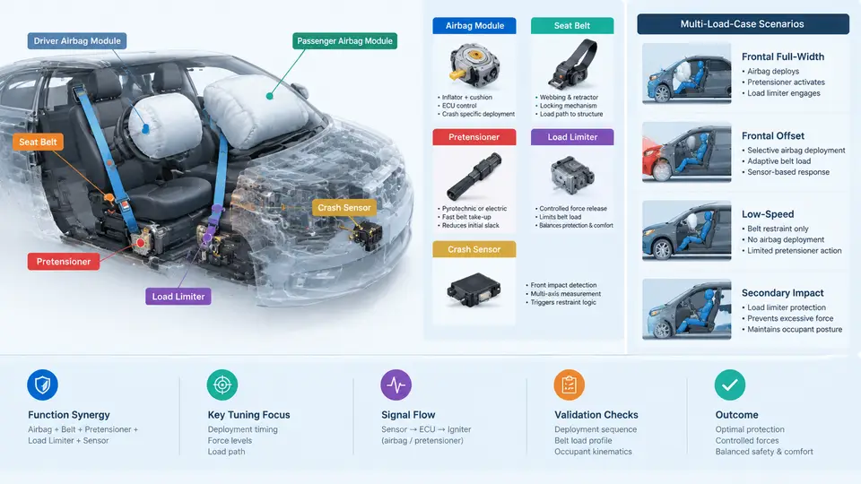
A frontal restraint system is not a single device but a coordinated chain of energy-absorbing and energy-dissipating elements that must behave differently depending on who is in the seat, how they are positioned, and how severe the crash is. In a multi-load-case development program, the architecture is judged not by how well it performs in one certification pulse, but by how consistently it manages occupant kinematics across low-speed, high-speed, out-of-position, and unbelted or small-occupant scenarios. This chapter establishes the physical architecture and the sensing logic that make that consistency possible.
The Restraint Chain and Its Energy Path
In a frontal impact, the vehicle decelerates first; the occupant continues forward until restrained. The restraint system's job is to couple the occupant to the vehicle's deceleration over the longest tolerable distance and time, while keeping peak loads on the body below injury thresholds. Four elements share that task:
- Seat belt webbing and geometry — the primary load path, transferring occupant force into the retractor, buckle, and anchor points.
- Retractor pretensioner — removes slack and pulls the occupant into the seat early in the event, reducing ride-down distance lost to belt slack.
- Load limiter — a force-limiting element (torsion bar in the retractor spool, or a stitch-rip / deformable anchor) that caps belt force once a threshold is reached, trading chest deflection against forward excursion.
- Airbag module — a supplemental path that distributes force over the chest and head, and in multi-stage form can be tuned to event severity.
The critical architectural insight is that these elements are tuned against each other. A stiffer load limiter paired with an aggressive airbag produces high chest compression; a soft load limiter with a late-firing airbag produces excessive forward excursion and head contact with the steering wheel or instrument panel. Multi-load-case calibration is largely the art of finding a force–time profile that satisfies all occupants simultaneously.
Airbag Module Architecture
A driver frontal airbag module comprises the inflator, the cushion, the module housing, and the cover. The inflator type determines the inflation profile: pyrotechnic inflators deliver fast, high-mass-flow gas; hybrid inflators combine a stored-gas charge with a pyrotechnic heater for a cooler, more sustained fill. Multi-stage inflators (dual-stage or variable-output) allow the restraint control module (RCM) to command different output levels — typically a low-output stage for lower-severity or out-of-position events and full output for high-severity events.
Passenger airbags add architectural complexity: the cushion must fill a larger volume, the module is mounted in the instrument panel, and the system often includes a passenger presence detection (POD) or occupant classification system (OCS) that can suppress deployment or select a lower output. Vent holes in the cushion are a calibration lever — larger vents bleed gas and soften the cushion late in the event, which matters for small occupants and out-of-position cases.
Seat Belts, Pretensioners, and Load Limiters
The retractor integrates three functions: webbing storage, locking (via a vehicle-sensitive or web-sensitive mechanism), and — in modern systems — pretensioning and load limiting. A pyrotechnic retractor pretensioner rotates the spool to retract webbing within milliseconds of the crash signal; buckle pretensioners pull the buckle stalk downward to tension the lap portion. The two are often used together to control both shoulder and lap belt geometry.
Load limiting is where multi-load-case trade-offs concentrate. A torsion-bar load limiter yields at a designed force level, allowing controlled webbing payout. Because chest deflection limits differ by occupant size and by regulatory versus consumer rating criteria, many systems use a switchable or adaptive load limiter: a second torsion bar or a pyrotechnically released element changes the limiting force based on occupant size, belt status, or crash severity. The table below summarizes the architectural levers and their primary multi-load-case effect.
| Element | Calibration lever | Primary multi-load-case effect |
|---|---|---|
| Retractor pretensioner | Pyro charge, retraction stroke, firing time | Reduces slack; earlier coupling improves low-speed and OOP outcomes |
| Load limiter | Torsion bar force level, switchable stage | Caps chest load; adaptive level protects small occupants |
| Airbag inflator | Stage output, fill rate, vent area | Severity-matched cushion stiffness; OOP risk reduction |
| Belt geometry | Anchor positions, D-ring height, buckle stalk | Load distribution across pelvis and chest; submarining control |
Crash Sensing and Deployment Logic
The RCM fuses signals from accelerometers (front-end and central tunnel) and, in many architectures, pressure or acceleration sensors in the front bumper or crash box. It computes a crash severity metric — often a velocity change estimate derived by integrating deceleration — and compares it against calibrated thresholds. The decision logic must satisfy two competing requirements: fire early enough to protect the occupant, but not so early that it deploys in low-speed events where the belt alone suffices, or in misuse events such as a hammer blow to the bumper.
Multi-load-case sensing adds a second dimension: severity discrimination. The RCM must distinguish, for example, a 25 km/h rigid-barrier impact from a 50 km/h full-frontal impact, and command different inflator stages and load-limiter states accordingly. This is typically implemented as a set of calibrated threshold curves (deceleration versus time, or velocity change versus time) with hysteresis to prevent chatter. The figure below shows the signal and decision chain from sensors through the RCM to the restraint actuators.
Why Multi-Load-Case Architecture Differs from Single-Pulse Design
A system optimized for one 50 km/h full-frontal barrier test can be made to pass with a relatively stiff belt, a strong load limiter, and a single-stage airbag. That same system may fail a 25 km/h low-severity test (too much restraint force for the occupant's forward momentum), an out-of-position test (airbag too aggressive at close range), or a small-occupant test (chest deflection exceeds the limit). Multi-load-case architecture therefore builds in adaptivity: switchable load limiters, multi-stage inflators, occupant classification, and severity-discriminating sensing. The calibration task is to define the switching thresholds and stage maps so that each load case lands in the correct branch of the decision tree.
Practical Calibration Considerations
In practice, the architecture is exercised through a matrix of load cases: regulatory frontal barriers at multiple speeds, offset deformable barrier tests, out-of-position static deployment tests, and sled tests with instrumented ATDs (anthropomorphic test devices) representing 5th-percentile female through 95th-percentile male occupants. For each case, the calibration engineer records chest deflection, head excursion, neck load, and femur load, and compares them against injury criteria. The architectural levers are then adjusted iteratively — a common starting point is to set the load limiter force from the chest deflection limit of the most restrictive occupant, then tune inflator stage timing to control head excursion without adding chest load.
A useful diagnostic pattern: if chest deflection is high across all occupants, the load limiter is too stiff or the airbag is over-aggressive; if head excursion is high while chest deflection is acceptable, the load limiter is too soft or the airbag is firing late. If results diverge sharply between small and large occupants, the switchable load limiter or occupant classification logic is the first place to look. These symptoms, read together with the sensing chain in the figure, give a structured starting point for calibration rather than trial-and-error.
The remaining chapters build on this architecture: sensing thresholds, inflator stage maps, load-limiter switching logic, and the test matrix that validates them. The key takeaway here is that the frontal restraint system is a tuned chain, and multi-load-case performance comes from making each link adaptive rather than from optimizing any single component in isolation.