4. Key sled test instrumentation
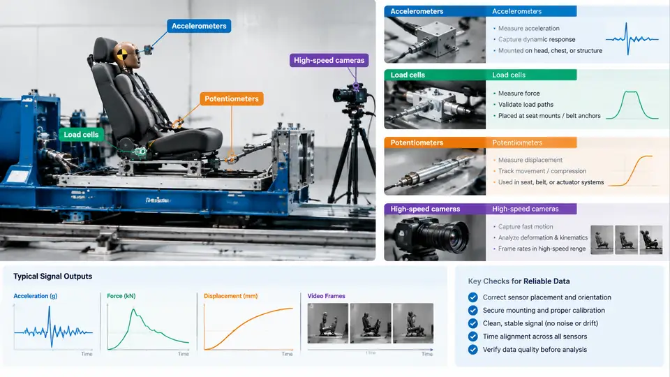
A frontal sled test is only as trustworthy as the measurement chain that captures it. The sled itself can reproduce a crash pulse with excellent repeatability, but if the accelerometers are misranged, a load cell is mounted with a preload offset, or the high-speed camera frame rate is too low to resolve the occupant's forward excursion, the resulting data will mislead every downstream decision — restraint tuning, airbag timing, or certification evidence. This chapter examines the four instrument families that carry the majority of the measurement burden in frontal sled work, how each is physically applied, and how their outputs are judged as valid or suspect.
Accelerometers: Capturing the Pulse and the Occupant Response
Accelerometers divide into two functional groups in a frontal sled. Sled-table accelerometers measure the input pulse that the crash pulse generator produces; they are the reference against which the test's severity is judged. On-board or anthropomorphic test device (ATD) accelerometers measure what the occupant or structure actually experiences — head resultant acceleration, chest acceleration, pelvis acceleration, and structural points of interest.
Selection is governed by range and frequency content. A frontal pulse typically peaks between 30 g and 60 g over 80–120 ms, but the head of a Hybrid III in a severe frontal event can briefly exceed 200 g. A practical rule is to choose a sensor whose full-scale range is at least 1.5× the expected peak, so that no channel clips. Piezoresistive accelerometers are the standard for crash work because they respond down to DC, which matters when integrating acceleration to obtain velocity change (Δv) and displacement. A sensor with a 1,000 Hz low-pass filter is common for ATD channels, while sled-table channels are often filtered at 300–1,000 Hz depending on the pulse's frequency content.
Mounting is where most accelerometer errors originate. The sensor must be rigidly coupled to the structure it is meant to measure; a soft mount or a bracket with a resonance inside the measurement band will produce a signal that reflects the bracket, not the body. For ATD head accelerometers, the triaxial block is seated in the head cavity per the dummy manufacturer's procedure, and the mounting bolts are torqued to specification. For sled-table measurement, the accelerometer is bolted directly to the table surface, aligned with the sled's longitudinal axis. Orientation matters: the SAE J211 sign convention defines positive longitudinal acceleration as forward (in the direction of travel), and every channel's polarity must be verified before the test, typically with a static tilt or a known-direction tap test.
Load Cells: Measuring the Forces That Restraints Impose
Load cells quantify the forces transmitted through restraint hardware. In a frontal sled, the most common applications are seat-belt load cells (webbing tension at the shoulder and lap), buckle load cells, seat-structure load cells, and steering-column or knee-bolster load cells. Each answers a different question: belt tension tells you how the restraint is loading the occupant; buckle force tells you the total restraint force path; seat load cells reveal how much load the seat transfers to the floor.
Strain-gauge load cells are the workhorse. Their output is small — typically 1–3 mV/V at full scale — so signal conditioning and cable routing are critical. A belt load cell is installed in-line with the webbing, and the webbing must be routed so that the load cell sees pure tension, not bending or side load. Before the test, the channel is zeroed with the belt at its normal pre-test tension; any residual preload becomes an offset that must be documented. During the test, the load cell's output is sampled at 10–20 kHz, well above the accelerometer rate, because belt forces contain high-frequency content from webbing stretch and buckle dynamics.
A frequent failure mode is a load cell that reads plausibly but is mechanically compromised — a bent mounting bracket, a partially slipped webbing, or a connector that has been strained. The tell is usually a force trace that is smoother or lower than the belt's expected loading profile, or a channel that fails a pre-test shunt calibration. Shunt calibration, in which a known resistor is switched across a bridge arm to simulate a known strain, is the standard verification that the entire channel — sensor, cable, conditioner, and DAQ — is alive and correctly scaled.
Potentiometers: Tracking Displacement and Excursion
Potentiometers (and their more modern string-potentiometer cousins) measure linear displacement. In frontal sled testing they are used to track belt payout, steering-wheel rearward displacement, pedal travel, seat cushion compression, and occupant forward excursion relative to the interior. A string potentiometer consists of a spring-loaded cable that extends from a housing; the cable's free end is attached to the moving object, and the housing to a fixed reference. As the object moves, the cable extends and the internal potentiometer's resistance changes proportionally.
The critical installation detail is the reference frame. A string pot measuring occupant excursion must have its housing mounted to the sled structure, not to the seat, if the seat itself is expected to deform. The cable must be routed so it does not snag on the ATD, the belt, or any interior trim, and it must be long enough that it never reaches its end stop during the event — a string pot that bottoms out produces a flat-topped trace that looks like a plateau but is actually a mechanical limit. Pre-test, the string pot is exercised through its expected travel range and its output is checked against a ruler; a linearity error greater than about 1% of full scale warrants replacement.
High-Speed Cameras: The Visual Ground Truth
High-speed cameras do not produce numerical channels, but they are indispensable because they let engineers see what the sensors cannot: belt routing, airbag deployment, occupant kinematics, and structural deformation. A frontal sled is typically covered by three to five cameras — a side view of the occupant, a front oblique view, an overhead view, and often a close-up on the belt path or the steering wheel.
Frame rate is chosen from the fastest event to be resolved. Airbag deployment and belt lock-up occur within the first 30–50 ms, so a camera capturing the occupant compartment is usually run at 1,000 frames per second (fps) or higher; a wide structural view may run at 500 fps. Resolution and frame rate trade off against each other and against available light, so the lighting plan is part of the camera setup, not an afterthought. Cameras are synchronized to the data acquisition system by a common trigger — typically the sled's release signal or a dedicated sync pulse — so that a frame at t = 40 ms corresponds to the same instant in the accelerometer and load-cell records. Without this sync, correlating a visible belt slip with a force trace is guesswork.
How the Instruments Work Together
The four instrument families are not independent; they cross-validate one another. A belt load cell's force trace should rise at the same instant the high-speed camera shows the belt locking; the occupant's head acceleration should peak near the frame where the camera shows maximum forward excursion; the string pot's displacement should integrate consistently with the sled-table acceleration. When one channel disagrees with the others, the disagreement itself is diagnostic — it usually points to a mounting error, a scaling error, or a mechanical limit rather than a genuine physical event.
Reading the Data: What Valid and Invalid Look Like
Once the test is complete, the first pass is a channel-by-channel sanity check before any engineering interpretation. An accelerometer trace that is flat during the pulse, or that shows a sharp discontinuity, usually indicates a cable fault or a sensor that has come loose. A load cell trace that is negative during belt loading suggests reversed polarity or a mis-wired bridge. A string pot trace that plateaus before the expected excursion indicates the cable has reached its end stop. A camera that shows the occupant moving but whose frame timestamps drift relative to the accelerometer record indicates a sync failure.
Only after these checks pass should the data be filtered per SAE J211 and integrated or compared. The instrumentation is the foundation of every conclusion drawn from a frontal sled test; treating the pre-test verification and post-test sanity check as seriously as the test itself is what separates a defensible validation program from a collection of plausible-looking traces.