1. Frontal crash safety landscape
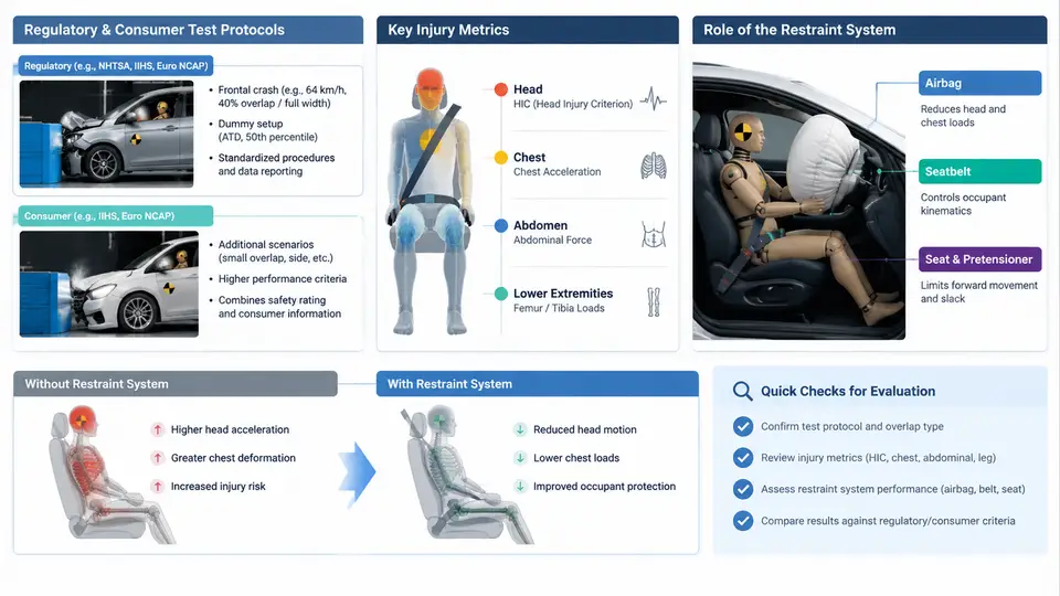
Frontal impacts remain the most frequent and most injurious crash mode in real-world traffic. Before a single restraint component is designed, the development team must understand the regulatory and consumer test environment that will ultimately judge the vehicle, the injury metrics those tests measure, and the specific role the restraint system plays in converting a violent deceleration event into a survivable occupant response. This chapter establishes that landscape and frames the engineering problem the rest of the course will solve.
Two Parallel Test Universes: Regulation and Consumer Rating
Frontal crash safety is governed by two distinct but overlapping test universes. Regulatory tests define legal minimums: a vehicle must pass to be sold. Consumer rating programs go beyond pass/fail and produce a comparative score that directly influences purchase decisions and manufacturer reputation. A restraint system optimized only to clear the regulatory threshold will typically score poorly in consumer tests, and vice versa; the calibration must satisfy both.
In the United States, FMVSS 208 is the central frontal regulation. It requires occupant protection in a rigid barrier test at 56 km/h (35 mph) with belted and unbelted dummies, and it includes an unbelted occupant requirement that strongly shapes airbag and knee-bolster design. Europe's ECE R94 and the newer UN R137 specify a 56 km/h offset deformable barrier (ODB) test at 40% overlap, which loads only part of the vehicle front and produces asymmetric occupant kinematics. China's GB 11551 follows a similar offset philosophy. These regulatory tests are pass/fail against injury criteria thresholds.
Consumer programs apply more demanding and more varied loading. Euro NCAP runs a 64 km/h ODB at 40% overlap plus a full-width rigid barrier test at 50 km/h, and it now scores a mobile progressive deformable barrier (MPDB) test that evaluates both occupant protection and compatibility with the opposing vehicle. IIHS in the United States uses a 40% overlap moderate-overlap test at 64 km/h and a 25% small-overlap test at 64 km/h, the latter being particularly punishing because the barrier misses the longitudinal rails and loads the wheel and A-pillar directly. C-NCAP and JNCAP add their own variants. The practical consequence is that a single restraint calibration must perform across a matrix of barrier types, overlaps, speeds, and dummy sizes.
Injury Metrics: What the Dummy Actually Reports
Crash test dummies instrument the body to produce physical measurements that are converted into injury criteria. The most important frontal metrics are:
- HIC (Head Injury Criterion) — derived from the resultant head acceleration over the impact duration, HIC36 and HIC15 are the common forms. Lower is better; regulatory limits are typically around 700–1000 depending on the test.
- Head acceleration (3 ms clip) — the peak acceleration sustained for 3 ms, limiting skull loading.
- Neck injury criteria (Nij, Nkm) — combine axial force and bending moment to capture neck injury risk, especially relevant in offset and small-overlap tests where the head loads asymmetrically.
- Chest deflection and Viscous Criterion (VC) — chest compression and the rate of compression, which correlate with rib fracture and internal organ injury. Chest deflection is often the binding constraint for belt and airbag tuning.
- Femur force and knee displacement — capture lower-extremity loading from the knee bolster and instrument panel.
- Combined injury probability — consumer programs aggregate these into a body-region score and an overall star rating.
Each metric responds differently to restraint parameters. HIC is dominated by head-to-airbag interaction and airbag venting; chest deflection is dominated by belt force limiting and pretensioner timing; femur force is dominated by knee-bolster stiffness and geometry. This is why restraint calibration is a multi-objective problem rather than a single tuning task.
The Restraint System's Role in the Load Path
The restraint system does not stop the occupant; it manages the occupant's deceleration over distance and time. In a frontal crash the vehicle front structure crushes and the occupant compartment decelerates. The occupant, by inertia, continues forward. The restraint system must couple the occupant to the decelerating compartment through a controlled force–deflection characteristic, spreading the load over the strongest body regions (pelvis, thorax, shoulder) and over the longest practical distance.
The primary elements are the seat belt (with pretensioner and load limiter), the frontal airbag, the knee bolster, and the seat structure. The belt provides the continuous restraint path; the pretensioner removes slack early in the event; the load limiter caps belt force to protect the chest; the airbag provides a compliant surface for the head and distributes upper-body load; the knee bolster controls pelvis and femur loading and helps position the occupant. The interaction of these elements — not any one alone — determines the injury outcome.
From Test Protocol to Design Target
The engineering translation is straightforward in principle but demanding in practice. Each test protocol defines a loading case: barrier type, overlap, speed, dummy size, and seating position. The restraint system must be calibrated so that, for every case in the matrix, the measured injury metrics stay below the applicable threshold with margin. Because the cases conflict — a stiff airbag that helps in a full-width test may over-load the head in a small-overlap test, and a soft load limiter that protects the chest may allow excessive head excursion — the calibration is a constrained optimization.
A practical starting point is to build a requirements table that maps each test case to its governing metrics and limits. For example, a development team might record that the 64 km/h ODB case is chest-deflection-critical, the 25% small-overlap case is head-and-neck-critical, and the unbelted FMVSS 208 case is airbag-volume-critical. That table then drives which parameters receive priority in CAE iteration and which physical tests are scheduled first.
| Test Case | Speed / Barrier | Governing Metric | Restraint Lever |
|---|---|---|---|
| FMVSS 208 belted | 56 km/h rigid | Chest deflection, HIC | Load limiter, airbag vent |
| FMVSS 208 unbelted | 56 km/h rigid | HIC, chest, femur | Airbag volume, knee bolster |
| ECE R94 / UN R137 | 56 km/h ODB 40% | Chest, femur | Belt force, pretensioner timing |
| Euro NCAP ODB | 64 km/h ODB 40% | Chest, head | Load limiter, airbag pressure |
| IIHS small overlap | 64 km/h 25% | Head, neck, chest | Side-curtain, belt geometry |
Why the Restraint System Is the Last Line of Defense
Vehicle structure can only absorb so much energy before the occupant compartment begins to deform. Once the structure has done its job, the restraint system is the only remaining mechanism that can reduce occupant injury. Its authority is large: a well-calibrated belt-and-airbag combination can reduce chest deflection by tens of millimeters and HIC by hundreds of points relative to an uncalibrated system. But that authority is bounded by the available ride-down distance and by the occupant's own tolerance. The engineer's task is to use the available distance and force budget as efficiently as possible across the entire test matrix.
This chapter has established the test landscape, the injury metrics that quantify occupant response, and the load-path role of the restraint system. The chapters that follow will move from this landscape into the detailed design and calibration of each restraint element, beginning with the belt system and its force-limiting behavior.