1. Frontal airbag system architecture
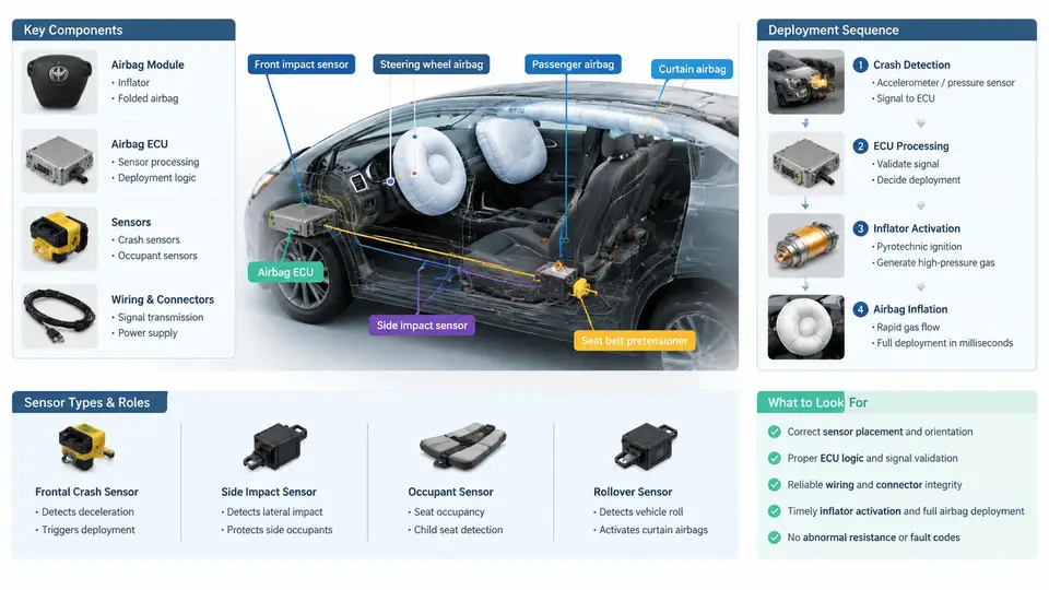
A frontal airbag is not a single device but a distributed, time-critical restraint subsystem. Its job is deceptively simple: decide within a few milliseconds whether a crash is severe enough to require deployment, then inflate a cushion fast enough to intercept an occupant who is already moving forward. Everything in the architecture — sensor placement, signal processing, the deployment loop, and the inflator — exists to satisfy that deadline. This chapter establishes the physical and logical structure of the system so that later analysis of deployment timing and occupant kinematics has a concrete reference frame.
1.1 The deployment loop as a closed control chain
The airbag system is best understood as a sensing-to-actuation chain with a hard real-time budget. The chain begins at the crash sensors, passes through signal conditioning and the airbag control unit (ACU, also called the SDM — sensing and diagnostic module), and terminates at the inflator squib. The ACU continuously evaluates a crash severity metric derived from deceleration; when that metric crosses a calibrated threshold within a defined time window, the ACU fires the squib, which initiates the inflator's gas-generating reaction and inflates the cushion.
Two timing quantities dominate the design. The decision time is the interval from impact (t = 0) to the firing command; typical frontal targets are on the order of 10–30 ms depending on crash mode and calibration. The inflation time is the interval from firing to the cushion reaching working pressure, typically 20–40 ms for a driver airbag. The sum must place a fully inflated cushion in front of the occupant before the occupant's forward excursion exceeds the available ride-down distance. This is why the architecture cannot be evaluated in isolation from occupant kinematics — the sensor and inflator are matched to a specific occupant and belt configuration.
1.2 Sensor types and their roles
Frontal systems use several sensor classes, each contributing a different piece of evidence:
- ACU-integrated accelerometer (central sensor). A MEMS accelerometer mounted rigidly to the vehicle floor tunnel or central body structure. It measures the vehicle's longitudinal deceleration directly and is the primary input to the deployment algorithm. Because it is centrally mounted, it is relatively insensitive to localized crush and captures the overall crash pulse.
- Front-end satellite sensors (upfront sensors). Accelerometers or pressure sensors mounted on the radiator support, crash box, or front bumper beam. They detect the crash earlier than the central sensor because they are closer to the impact point, providing a few milliseconds of lead time that improves discrimination between, for example, a soft offset impact and a rigid pole strike.
- Pressure-based side/front sensors. In some architectures, a pressure sensor inside a door cavity or bumper structure detects the rapid pressure rise caused by deformation. These are more common in side restraint systems but appear in frontal architectures for pedestrian and low-speed discrimination.
- Safety sensors (crash switches). A mechanical or solid-state switch in series with the squib circuit that closes only above a defined deceleration, providing a redundant arming path independent of the microcontroller.
- Occupant and environment inputs. Seat track position sensors, belt buckle switches, occupant weight/classification sensors, and roll-rate sensors feed the ACU so the deployment decision and inflator output can be adapted (dual-stage or multi-stage inflators, suppressed deployment for out-of-position occupants).
The essential architectural principle is redundancy with diversity: the central accelerometer and the front-end satellites use different mounting locations and often different sensing physics, so a single sensor failure or a localized false trigger does not produce an incorrect deployment. The safety sensor adds an independent hardware gate.
1.3 Inside the ACU: signal path and deployment logic
The ACU contains the accelerometer, analog front-end, microcontroller, squib driver (a high-side/low-side FET pair or an application-specific firing ASIC), backup energy reserve (a capacitor that guarantees firing energy for a short period after battery disconnect), and diagnostic circuitry. The signal path is:
- Acquisition. Accelerometer output is sampled at a high rate (commonly 1–10 kHz) and filtered with a low-pass characteristic to remove structural ringing while preserving the crash pulse.
- Feature extraction. The ACU computes velocity change by integrating the filtered deceleration, and often a windowed energy or jerk metric. Integration is the key step: a short, high-amplitude spike (a pothole or hammer blow) produces little velocity change, whereas a sustained crash pulse produces a large one.
- Threshold comparison. The severity metric is compared against a calibration map that is a function of time and, in advanced systems, of satellite sensor confirmation. The map is deliberately time-varying: an early, high threshold prevents deployment on rough-road events, while a lower threshold later in the event captures softer but still injurious crashes.
- Firing decision and squib actuation. When the metric crosses the threshold and the safety sensor is closed, the driver discharges the energy reserve through the squib. Squib resistance is monitored continuously; an open or shorted squib sets a diagnostic trouble code and may inhibit deployment.
1.4 The inflator and cushion
The inflator converts the electrical firing pulse into gas. Two dominant types are used in frontal systems. Pyrotechnic inflators burn a solid propellant (e.g., sodium azide-based or guanidine nitrate-based compositions) to generate gas directly. Hybrid inflators combine a small pyrotechnic charge with a stored compressed gas (argon/helium), giving a cooler, more controllable fill and enabling dual-stage output. Dual-stage inflators contain two independent squibs and charges; the ACU can fire one or both, or fire them with a time offset, to tailor cushion pressure to crash severity and occupant size.
The cushion itself is folded in a specific pattern so that it unfolds along a controlled trajectory — typically upward and rearward from the steering wheel or instrument panel — rather than directly toward the occupant. Vent holes in the cushion regulate pressure during occupant loading, providing the ride-down that converts occupant kinetic energy into controlled deceleration. The combination of inflator output, vent area, and cushion volume determines the pressure-time history that the occupant actually experiences.
1.5 Architecture at a glance
The figure below summarizes the deployment loop as a signal-and-energy chain, showing the parallel sensing paths, the ACU decision stage, and the actuation path to the inflator. It is a structural reference for the timing analysis in later chapters.
1.6 What the architecture implies for timing analysis
Three consequences follow directly from this structure and set up the rest of the course. First, the deployment decision is a threshold-crossing event on an integrated signal, so the crash pulse shape — not just its peak — determines when firing occurs. A stiff, short pulse and a soft, long pulse can have the same peak deceleration but very different decision times. Second, the satellite sensors buy lead time; their value is measured in milliseconds of earlier confirmation, which is why their mounting stiffness and location are calibrated as carefully as the algorithm itself. Third, the inflator and cushion are matched to the occupant: dual-stage output and vent sizing exist because the same cushion must serve a 50th-percentile male and a small female, belted and unbelted, at different seat positions.
When you later examine a deployment timing trace or reconstruct occupant kinematics, return to this chain. Every millisecond in the trace belongs to a specific stage — sensing latency, filtering group delay, integration window, threshold logic, squib firing, and inflator burn — and knowing which stage dominates is the first step in diagnosing either a late deployment or an unnecessary one.