4. Occupant kinematics reconstruction from
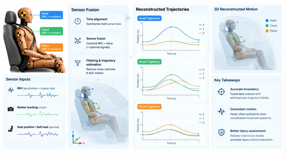
Crash test data rarely arrives as a clean trajectory. A sled or full-vehicle test produces accelerometer channels on the vehicle structure, accelerometer and angular-rate channels on the Hybrid III or THOR dummy, high-speed video from multiple camera angles, and often string potentiometers or optical targets on specific body segments. Each source measures something different, at a different rate, in a different reference frame, and with its own error structure. Reconstructing where the head, chest, and pelvis actually went — and when — is a sensor fusion problem before it is an injury-criteria problem. This section covers the practical pipeline: defining a consistent coordinate convention, integrating and drift-correcting accelerometer data, registering video-derived marker positions, and fusing the two into a single defensible trajectory per body segment.
Establish a single coordinate and sign convention first
Every downstream number inherits the sign convention chosen at the start. Adopt the SAE J211 / ISO 6487 vehicle axis system and state it explicitly in the analysis log: +X forward (direction of travel), +Y to the occupant's right, +Z upward, with rotations positive according to the right-hand rule. Dummy-mounted accelerometers are typically oriented in the dummy local frame, which for an upright, nominally seated occupant coincides with the vehicle frame only at t = 0. Record the mounting orientation matrix for each sensor; a chest triaxial block rotated 90° about Z will otherwise silently swap X and Y contributions. All filtering follows the same standard: low-pass at the channel class frequency (CFC 60 for occupant accelerations, CFC 180 or 1000 for structural channels), applied with a zero-phase filter so that no artificial time shift is introduced between channels that will later be fused.
From acceleration to displacement: double integration and drift control
Head and chest CG accelerations are integrated twice to obtain displacement. Raw double integration is unstable because any residual bias or offset accumulates quadratically. The standard mitigation is a two-stage approach: high-pass or detrend the acceleration before the first integration, then apply a linear (or low-order polynomial) baseline correction to the velocity so that the final velocity returns to zero at the end of the event window. A practical sequence for a 200 ms frontal pulse sampled at 10 kHz:
% a: filtered acceleration (m/s^2), t: time vector (s), fs = 10000
a_detr = a - polyval(polyfit(t, a, 1), t);      % remove linear bias
v      = cumtrapz(t, a_detr);                    % first integration
v_corr = v - polyval(polyfit([t(1) t(end)], [v(1) v(end)], 1), t);
d      = cumtrapz(t, v_corr);                    % second integration
d      = d - d(1);                               % zero at t0
The correction endpoints matter. If the dummy is still moving at the end of the window, forcing v(end) = 0 injects a false deceleration ramp. Choose the window to end after the occupant has settled against the restraint, and cross-check the residual displacement against the video-derived position at the same instant. A discrepancy above roughly 15–20 mm at the head for a 50 km/h frontal test is a signal that the bias correction or the window boundary needs revisiting, not that the video is wrong.
Video-derived marker trajectories
High-speed video at 1000 fps gives direct position but coarse temporal resolution and pixel-level noise. Track retro-reflective targets or painted markers on the head (often the head CG target on the dummy skull cap), the chest (sternum or upper-spine target), and the pelvis (H-point or iliac target). Camera calibration via a known target board establishes the pixel-to-millimeter scale and the camera pose; for stereo or multi-camera setups, triangulation yields 3D positions, while a single orthogonal camera gives a planar projection that must be reconciled with the accelerometer-derived out-of-plane motion. Smooth the tracked coordinates with the same CFC 60 filter used on the accelerometers so that both sources share an identical passband — fusing channels filtered at different cutoffs produces phase artifacts that look like real kinematic events.
Fusion strategy and cross-validation
The two sources are complementary: accelerometers are precise in the high-frequency band but drift at low frequency; video is absolute and drift-free but noisy and band-limited. A defensible fusion is a complementary filter or a simple weighted blend in the frequency domain — trust the integrated acceleration above roughly 10–15 Hz and the video-derived position below it. In practice, many labs use the video trajectory as the reference and apply a slowly varying offset correction to the integrated acceleration so that the two agree at the start, at peak excursion, and at the end of the event. The figure below shows the fusion architecture and the cross-check points that gate acceptance.
Worked example: a 50 km/h frontal sled test
Consider a representative frontal sled test with a belted Hybrid III 50th percentile male, pulse onset at t = 0, event window 0–200 ms. The head X accelerometer peaks near 75 g at about 65 ms; the chest X channel peaks near 45 g at about 55 ms; the pelvis X channel peaks near 40 g at about 45 ms. After detrending and double integration with endpoint velocity correction, the head CG reaches a forward excursion of roughly 320 mm at about 110 ms before the belt and airbag load path pull it back. The video-derived head target, triangulated from two calibrated cameras, gives approximately 310 mm at the same instant. The 10 mm difference is within the acceptance band and is consistent with the accelerometer branch slightly over-integrating during the high-jerk phase; the fused curve adopts the video value at peak and blends the branches elsewhere.
Two failure symptoms are worth recognizing. First, if the head trajectory shows a monotonic forward drift that never returns toward the seat-back reference by the end of the window, the velocity baseline correction is almost certainly wrong — check whether the integration window extends past the point where the head has rebounded and whether the linear fit was applied over the correct interval. Second, if the chest and pelvis trajectories appear to move in opposite Z directions during the ride-down phase, suspect a sign error in one sensor's mounting orientation matrix rather than a real kinematic effect; a chest block mounted upside down will invert the Z channel and produce exactly this artifact. Both are caught by the cross-check gates in the figure before any injury criterion is computed.
The output of this stage is a set of three time-aligned trajectory channels — head CG, chest CG (or upper spine), and pelvis — expressed in the vehicle frame, on a common time base, with documented filter class and fusion crossover. These channels feed directly into the relative-displacement and velocity computations used for head-to-interior contact assessment, belt-to-chest loading analysis, and the kinematic phase identification that precedes injury criteria evaluation.