4. Airbag system architecture
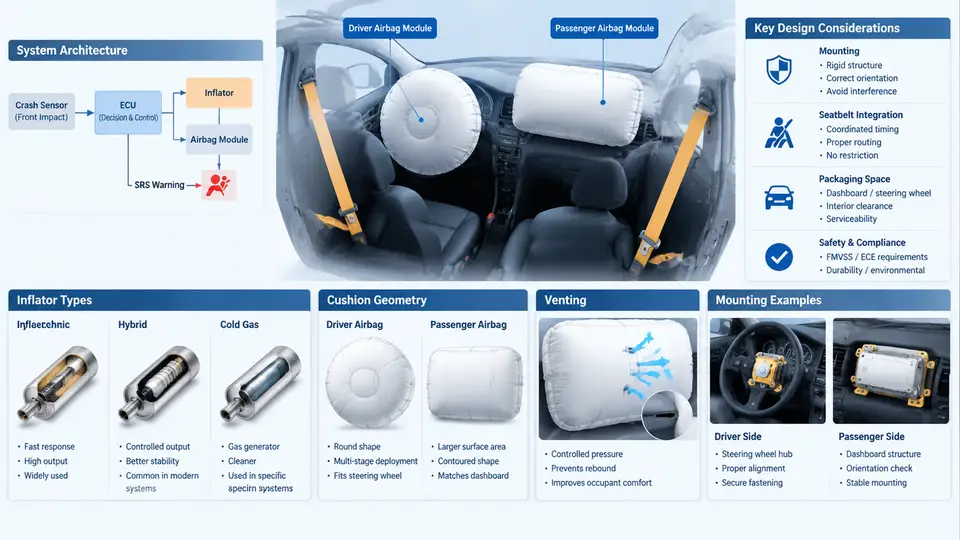
A frontal airbag is not a single component but a small, tightly integrated subsystem. Understanding its architecture means understanding how the module housing, inflator, cushion, venting strategy, and mounting interface work together to deliver a controlled deceleration pulse to the occupant. This section walks through each element and the engineering trade-offs that connect them, with attention to the differences between driver and passenger positions.
Module Architecture Overview
A frontal airbag module consists of four functional layers: the inflator (gas generator), the cushion (the fabric bag), the module housing and cover, and the mounting and retention structure. The inflator produces gas on command from the airbag control unit (ACU); the cushion captures and distributes that gas; the housing holds the folded cushion and directs deployment; and the mounting structure transfers reaction loads into the vehicle body or steering wheel.
The driver module is typically integrated into the steering wheel hub, with the inflator mounted coaxially behind the cushion. The passenger module sits in the instrument panel, usually on the passenger side, with the inflator offset from the cushion centerline and the cushion deploying upward and rearward through a tear seam in the IP. These two positions impose fundamentally different constraints: the driver module must fit within a small hub envelope and deploy toward a belted occupant at a fixed distance, while the passenger module must fill a much larger volume and manage an unbelted occupant who may be out of position.
Inflator Types and Selection
Three inflator families dominate frontal airbag design, and the choice drives much of the module's packaging and performance envelope.
Pyrotechnic inflators burn a solid propellant (typically sodium azide or a non-azide formulation) to generate gas directly. They are compact, fast, and inexpensive, but their output is essentially fixed once the grain is designed. They are common in driver modules where the required gas volume is modest (roughly 50–70 L for a driver cushion).
Hybrid inflators combine a small pyrotechnic charge with a stored compressed gas (often argon or helium). The burning charge heats and releases the stored gas, giving a higher gas yield per unit of propellant and a cooler, cleaner output. Hybrids are widely used in passenger modules, where cushion volumes of 100–150 L demand more gas than a pure pyrotechnic unit can economically provide.
Stored-gas inflators rely primarily on a pressurized gas reservoir released by a small squib. They are less common in production frontal systems today but appear in some architectures where very fast, cool inflation is desired. Their main drawback is the mass and packaging penalty of the pressure vessel.
Selection is driven by cushion volume, required fill time (typically 20–40 ms to full deployment for frontal systems), available packaging space, and cost. A useful rule of thumb: match the inflator's gas output curve to the cushion volume and vent area so that internal pressure peaks at the right moment relative to occupant contact.
Cushion Geometry
Cushion geometry determines how the bag interacts with the occupant. For the driver, the cushion is typically a toroidal or "donut" shape with a central recess that accommodates the steering wheel hub, giving a roughly 60–70 L volume and a face that presents a broad, flat contact surface to the chest and head. The driver cushion must also clear the steering wheel rim during deployment, so its folded pattern and the housing's breakout direction are carefully matched.
Passenger cushions are larger and more asymmetric. They must span the width of the passenger seating position, fill the space between the IP and the occupant, and often include internal tethers or a shaped profile to direct the bag toward the occupant rather than upward into the windshield. A typical passenger cushion is 100–150 L, with a depth of 500–700 mm from the IP face. Tethers sewn inside the bag control the final shape and prevent excessive rearward penetration.
Key geometric parameters include cushion volume, face area, depth, and tether configuration. These are tuned together with venting to shape the pressure-time curve.
Venting Strategy
Vents are the primary means of controlling cushion pressure after peak inflation. Without venting, the cushion would remain stiff and could injure the occupant; with excessive venting, the cushion would bottom out and fail to provide adequate restraint. Vent area is typically expressed in square millimeters and is tuned to the inflator output and cushion volume.
Common venting approaches include fixed vents (permanent holes in the cushion fabric), active vents (vents that open or close based on pressure or occupant position), and vent patches that tear open at a designed pressure. Fixed vents are simple and reliable; active vents allow adaptive performance for different occupant sizes and positions. The vent location matters: vents placed near the occupant contact face affect pressure differently than vents on the side or rear of the cushion.
A practical tuning example: for a driver cushion of 65 L with a pyrotechnic inflator, a total vent area of roughly 2,000–3,000 mm² is a common starting point, adjusted based on sled test pressure data. The goal is a pressure peak that occurs just as the occupant contacts the cushion, followed by a controlled decay.
Mounting Considerations
Mounting is where architecture meets the vehicle. The driver module mounts to the steering wheel armature through a retention ring or snap feature, and the module must be oriented so the cushion deploys along the steering column axis. The mounting must withstand the reaction force of deployment (several kN) without separating, and the cover must tear predictably along its seam.
The passenger module mounts to the IP structure or a dedicated cross-car beam. Because the passenger cushion is larger and the inflator is offset, the mounting must resist asymmetric reaction loads. The IP tear seam must be designed to open cleanly at the specified deployment force, and the module must be positioned so the cushion deploys into free space rather than into the windshield or A-pillar.
Putting It Together: A Design Review Checklist
The following checklist captures the key integration points an engineer should verify when reviewing a frontal airbag module design. It is a working example, not a universal standard.
| Area | Check | Typical Criterion (Example) |
|---|---|---|
| Inflator | Gas output vs. cushion volume | Fill to 90% within 25–35 ms |
| Cushion | Volume and tether configuration | Driver 60–70 L; passenger 100–150 L |
| Venting | Total vent area and location | 2,000–3,000 mm² (driver, example) |
| Mounting | Reaction load path and fastener preload | No separation at deployment reaction |
| Cover / tear seam | Breakout force and direction | Opens along seam without fragmenting |
These values are illustrative starting points for discussion; actual targets come from the vehicle's crash pulse, occupant packaging, and regulatory requirements. The architecture is only as good as the integration between these five elements, and the driver and passenger positions each demand their own tuning.