1. Program delivery framework for occupant
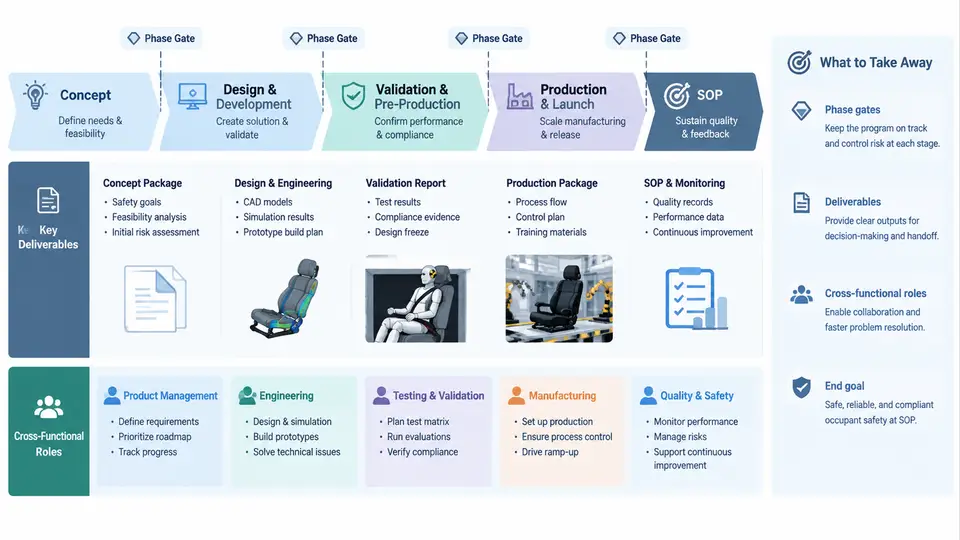
Occupant safety development is not a single engineering activity; it is a program that must move a vehicle from an initial safety intent to a verified, certified, and manufacturable restraint system. The framework that governs this movement is built on three interlocking elements: phase gates that control progression, deliverables that prove readiness at each gate, and cross-functional roles that own those deliverables. Without this structure, teams tend to optimize locally — a restraint engineer tunes a load limiter, a body engineer adds a reinforcement, a CAE analyst runs a sled model — and the program discovers integration failures late, when tooling is already committed.
This chapter establishes the delivery framework that the remaining chapters will populate with detailed methods. The goal is not to memorize a gate list but to understand why each gate exists, what must be demonstrated to pass it, and who is accountable when it does not pass.
Why a Phase-Gate Framework Is Necessary
Occupant safety performance is a system-level property. It emerges from the interaction of body structure, restraint geometry, airbag deployment, seat design, and occupant position. Each of these subsystems is developed by a different function, often on a different timeline. A phase-gate framework synchronizes these timelines by forcing integration points where evidence is reviewed against objective exit criteria.
The alternative — a continuous, gate-free development — typically produces three failure patterns. First, late discovery: a sled test at the prototype stage reveals that the seat belt anchor geometry cannot achieve the target chest deflection, but the body-in-white (BIW) hard points are already frozen. Second, unowned interfaces: the airbag module and the seat structure each meet their individual requirements, but the interaction between them produces an out-of-position (OOP) risk that no single team owns. Third, unverifiable claims: a supplier reports that a pretensioner meets its specification, but the evidence is a component bench test that does not represent the vehicle-level pulse.
Phase gates address these patterns by requiring that integration evidence, not just component evidence, is reviewed before the program advances.
The Phase-Gate Structure from Concept to SOP
A typical occupant safety program passes through six gates. The names vary by OEM, but the logic is consistent.
| Gate | Program Stage | Core Question | Typical Occupant Safety Evidence |
|---|---|---|---|
| G0 | Concept | Is the safety target feasible within the vehicle package? | Target cascade, package study, regulatory scan, concept CAE |
| G1 | Concept freeze | Are the restraint and structure concepts defined and compatible? | Concept sled CAE, restraint layout, airbag volume estimate |
| G2 | Design freeze | Are the hard points and subsystem specifications frozen? | Design verification plan (DVP), CAE correlation plan, supplier specs |
| G3 | Prototype build | Do physical prototypes meet the design intent? | Prototype sled tests, component bench tests, build audit |
| G4 | Pre-production | Does the production-intent system meet all targets? | Full-vehicle crash tests, OOP tests, certification pre-tests |
| G5 | SOP | Is the system certified, capable, and controlled? | Homologation reports, PPAP, control plan, field monitoring plan |
Each gate has an exit review. The review is not a status meeting; it is a decision point where the program either passes, passes with conditions, or is held. A hold at G3, for example, means prototype sled performance does not meet the target and the root cause must be identified before pre-production tooling is released.
Deliverables: What Proves Readiness
Deliverables are the evidence package for each gate. They fall into four categories.
- Requirements and targets: the safety target cascade from vehicle-level (e.g., US NCAP 5-star, Euro NCAP star rating, FMVSS 208 compliance) down to subsystem specifications (belt load limit, airbag vent size, seat frame stiffness).
- Analytical evidence: CAE models, correlation reports, and sensitivity studies that show the design is robust to variation.
- Physical evidence: sled tests, component tests, full-vehicle tests, and OOP tests with instrumentation data.
- Compliance evidence: regulatory test reports, homologation documents, and certification plans.
A common mistake is to treat CAE as a substitute for physical testing at early gates. CAE is appropriate for concept screening and design space exploration, but it must be correlated against physical tests before it can be used as primary evidence at G3 and beyond. The correlation plan is itself a deliverable at G2.
Cross-Functional Roles and Accountability
Occupant safety is delivered by a matrix of functions. The framework assigns a single accountable owner for each deliverable, even when multiple teams contribute.
| Role | Primary Responsibility | Key Deliverable at Gates |
|---|---|---|
| Occupant Safety Lead | Owns the safety target cascade and overall restraint system performance | Target cascade, DVP, gate evidence package |
| Restraint Engineer | Belt, pretensioner, load limiter, airbag module specification | Subsystem specs, component test reports |
| Body/Structure Engineer | BIW crash structure, hard points, seat mounting | Body CAE, hard point freeze, structural test reports |
| CAE Analyst | Model build, correlation, sensitivity and robustness studies | Correlation report, CAE evidence at each gate |
| Test Engineer | Sled, component, and full-vehicle test execution and instrumentation | Test reports, raw data, instrumentation logs |
| Seat Engineer | Seat structure, foam, head restraint geometry | Seat CAE, seat test reports, OOP position studies |
| Program Manager | Gate scheduling, risk tracking, cross-functional issue resolution | Gate review minutes, risk register, action log |
| Compliance/Homologation | Regulatory interpretation, certification planning | Regulatory scan, homologation plan, certification reports |
The critical interface is between the Occupant Safety Lead and the Program Manager. The Safety Lead owns the technical content of the gate evidence; the Program Manager owns the process and ensures that all functions deliver on time. When a gate is held, the Safety Lead defines the technical closure criteria and the Program Manager tracks the actions.
How the Framework Operates in Practice
Consider a program targeting Euro NCAP 5-star with a frontal offset deformable barrier (ODB) test at 64 km/h. At G0, the Safety Lead cascades the target into a chest deflection limit of 42 mm and a head injury criterion (HIC) limit of 700 for the 50th percentile male. The CAE analyst builds a concept sled model with a baseline restraint system. The restraint engineer proposes a 4 kN load limiter and a 120 L airbag. The body engineer confirms that the front rail crush space can absorb the required energy.
At G1, the concept sled CAE predicts a chest deflection of 45 mm — above target. The team evaluates three options: reduce the load limiter to 3.5 kN, increase airbag venting, or add a seat belt pretensioner with a higher retraction force. The CAE analyst runs a design of experiments (DOE) with these three factors. The result shows that the load limiter has the strongest effect, and a 3.5 kN setting brings the prediction to 40 mm. The concept is frozen with this setting.
At G2, the design is frozen and the DVP is written. The DVP specifies a sled test matrix: three repeats at the target pulse, two off-nominal pulses (severe and mild), and two OOP positions (in-position and out-of-position). The correlation plan requires that the CAE model match the sled test within 10% for chest deflection and 15% for head acceleration.
At G3, the first prototype sled test is run. The measured chest deflection is 44 mm — the CAE predicted 40 mm. The correlation is outside the 10% tolerance. The CAE analyst investigates and finds that the belt slip through the D-ring was underestimated in the model. The model is updated, and a second sled test confirms 41 mm. The gate is passed with a condition: the updated model must be used for all subsequent CAE evidence.
At G4, full-vehicle tests are run. The chest deflection is 41 mm, HIC is 680, and the OOP tests pass. The compliance team prepares the homologation documents. At G5, the control plan is finalized, and the program is released to SOP.
Common Pitfalls and How the Framework Prevents Them
Pitfall 1: Gate reviews become status updates. If the review does not have objective exit criteria, it becomes a presentation. The framework requires that each gate has a written checklist of evidence, and the review is a pass/fail decision against that checklist.
Pitfall 2: CAE is used beyond its validated range. A model correlated for a 50th percentile male frontal impact is not valid for a 5th percentile female side impact without re-correlation. The framework requires that the correlation plan define the valid range, and any use outside that range is flagged as a risk.
Pitfall 3: Interface ownership is ambiguous. The interaction between the airbag and the seat is a classic example. The framework assigns the interface to the Occupant Safety Lead, who must ensure that both the restraint engineer and the seat engineer provide evidence for the combined system, not just their individual components.
Pitfall 4: Supplier evidence is accepted without vehicle-level validation. A supplier bench test may use a different pulse, temperature, or mounting condition. The framework requires that supplier evidence is reviewed against the vehicle-level DVP, and any gap is closed with a vehicle-level test.
Summary
The phase-gate framework for occupant safety delivery is built on six gates from concept to SOP, each with defined exit criteria and evidence requirements. Deliverables span requirements, analysis, physical testing, and compliance. Cross-functional roles are assigned with single-point accountability for each deliverable, and the Occupant Safety Lead owns the technical integrity of the gate evidence. The framework prevents late discovery, unowned interfaces, and unverifiable claims by forcing integration evidence at each gate. The remaining chapters will detail the methods, tools, and data that populate this framework.