1. Occupant restraint system overview
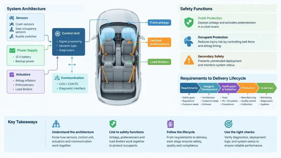
An occupant restraint system (ORS) is the coordinated set of components that decelerates and positions vehicle occupants during a crash so that injury metrics stay within regulated and consumer-rating limits. It is not a single part but a distributed safety subsystem whose behavior depends on sensing, decision logic, energy management, and structural interfaces working together within milliseconds. This chapter establishes the system architecture, the safety functions each element performs, and the lifecycle that carries requirements from concept to series delivery.
System Architecture
A modern ORS is organized into four functional layers: sensing, control, actuation, and structural/energy-management interfaces. The sensing layer includes frontal and side accelerometers, pressure-based side-impact sensors, seat-position and occupant-classification sensors, buckle switches, and rollover gyroscopes. The control layer is the Airbag Control Unit (ACU), which hosts crash algorithms, safing logic, and diagnostic supervision. The actuation layer covers frontal airbags (driver, passenger), side airbags (thorax, pelvis), curtain airbags, seat-belt pretensioners, load limiters, and increasingly active devices such as motorized seat-belt retractors. The structural layer includes the seat frame, steering column, instrument panel, and body-in-white load paths that determine how crash energy reaches the occupant.
These layers are connected primarily over a dedicated safety bus, typically a high-speed CAN or PSI5 interface for satellite sensors, with hardwired deployment loops for the firing circuits. The ACU continuously monitors loop resistance and sensor plausibility; a fault outside the defined window triggers a diagnostic trouble code (DTC) and may inhibit deployment for the affected loop while keeping others active.
Safety Functions
The ORS performs five core safety functions. First, crash detection and discrimination: the ACU must distinguish a deployment-relevant event from rough-road noise, door slams, or low-speed impacts within a tight time window. Second, occupant classification: the system determines whether a seat is occupied, the occupant's size/weight class, and whether a rear-facing child seat is present, so that passenger airbag deployment can be suppressed or derated. Third, energy management: pretensioners remove belt slack, load limiters cap belt force to reduce chest deflection, and airbags distribute pressure over a larger area. Fourth, out-of-position (OOP) protection: the system must not cause injury when an occupant is close to the airbag module at deployment. Fifth, diagnostics and fail-safe behavior: the system must warn the driver of faults and avoid unintended deployment.
These functions are quantified by requirements. For example, FMVSS 208 specifies frontal barrier and offset deformable barrier tests with injury criteria such as HIC 15 ≤ 700, chest deflection ≤ 63 mm, and femur axial force ≤ 10 kN for the 50th-percentile male dummy. Euro NCAP adds mobile progressive deformable barrier and far-side tests. The ORS must satisfy these across a matrix of speeds, overlap percentages, occupant sizes, and seat positions.
Requirements-to-Delivery Lifecycle
The lifecycle begins with requirements capture. Regulatory texts, consumer-rating protocols, and OEM internal standards are decomposed into system-level requirements: deployment thresholds, timing windows, suppression conditions, and diagnostic coverage. Each requirement is traced to a verification method — analysis, simulation, or physical test.
During design and CAE, engineers build sled and full-vehicle finite element models. A typical frontal sled model uses a deceleration pulse derived from the barrier test, with the seat, belt, airbag, and dummy modeled explicitly. The airbag is often represented by a uniform-pressure or corpuscular-particle method; the belt by shell and seat-belt elements with slip rings. The output is a time history of dummy injury metrics. If HIC exceeds the target, engineers adjust airbag vent size, tether length, or load-limiter force level.
Validation follows with physical sled tests, then full-vehicle barrier tests. The sled test isolates the restraint system from body crush, making it the primary tool for tuning. A typical sled test matrix might include 16 km/h, 25 km/h, and 50 km/h at 0°, 15°, and 30° angles, with 5th-percentile female, 50th-percentile male, and 95th-percentile male dummies. OOP tests use static deployment with the dummy at defined positions per FMVSS 208.
Homologation confirms compliance with the applicable regulation in each market. This includes witness testing at an accredited facility, documentation of the test matrix, and submission of the type-approval dossier. Series delivery covers production part approval (PPAP), end-of-line (EOL) testing of the ACU and firing loops, and traceability of safety-critical components. After start of production (SOP), field data and warranty returns feed back into the requirements, closing the loop.
Worked Example: Frontal Sled Tuning
Consider a frontal sled test at 50 km/h with a 50th-percentile male dummy. The baseline configuration uses a 4 kN load limiter and a 60 L driver airbag with two 25 mm vents. The measured HIC 15 is 780, above the 700 target, and chest deflection is 58 mm, within the 63 mm limit. The engineer increases vent diameter to 30 mm to reduce airbag pressure and adds a 3.5 kN load limiter. The revised simulation predicts HIC 15 = 660 and chest deflection = 61 mm. A physical sled test confirms HIC 15 = 675 and chest deflection = 60 mm, both within limits. The change is documented in the design verification plan and released for the next build phase.
| Lifecycle Phase | Key Input | Primary Output | Verification Method |
|---|---|---|---|
| Requirements | FMVSS 208, Euro NCAP, OEM standard | System requirement specification | Traceability review |
| Design & CAE | Sled pulse, CAD geometry, material data | FE model, injury metric predictions | Simulation correlation |
| Validation | Prototype hardware, test matrix | Sled and barrier test reports | Physical test |
| Homologation | Type-approval dossier | Regulatory approval | Witness testing |
| Series Delivery | Production parts, EOL spec | PPAP, SOP | EOL test, audit |
Understanding this architecture and lifecycle is the foundation for every subsequent chapter. The next sections will examine each layer in detail, starting with the regulatory and consumer-rating requirements that define the ORS design targets.