1. Introduction to automotive restraint sys
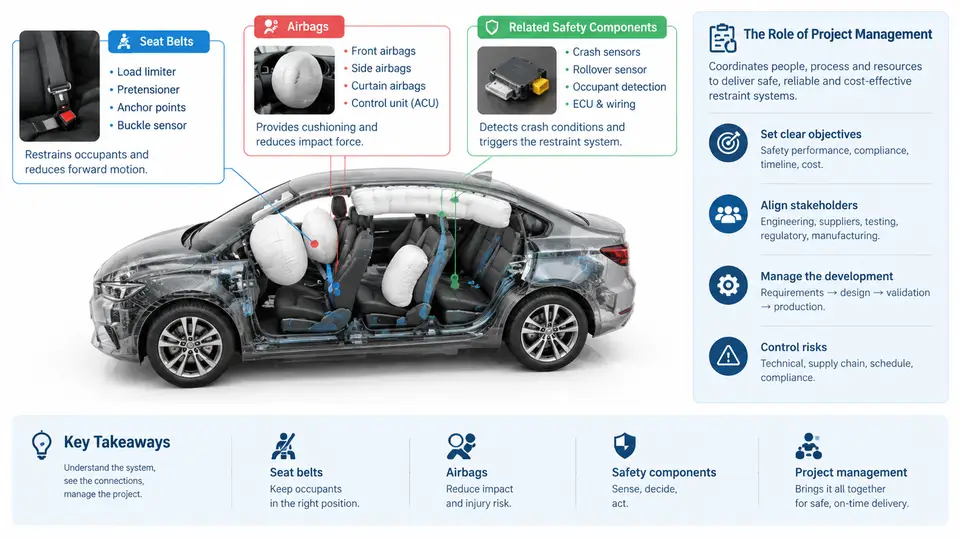
An automotive restraint system is the collection of components that decelerates and positions occupants during a crash so that the forces acting on their bodies stay within survivable limits. It is not a single product but a coordinated safety subsystem. The seat belt is the primary restraint; airbags are supplemental restraints that distribute load over a larger area. Together with seat structures, pretensioners, load limiters, occupant sensors, and the electronic control unit (ECU) that arbitrates deployment, they form what engineers call the occupant restraint system (ORS).
Understanding this system is the foundation of restraint project management. A project manager (PM) does not design the airbag cushion or tune the retractor, but must understand how these parts interact, which requirements drive them, and how their development timelines interlock with vehicle milestones. This chapter establishes that shared vocabulary.
What the System Contains
A typical passenger-car restraint system includes the following functional groups:
- Seat belt assemblies — retractor, webbing, tongue and buckle, anchorages, height adjuster, and often a pretensioner and load limiter.
- Airbag modules — driver frontal, passenger frontal, side thorax, side curtain, knee, and increasingly far-side airbags, each with an inflator and cushion.
- Crash sensors — accelerometers and pressure sensors mounted in the front end, B-pillars, doors, and sometimes the floor tunnel.
- Restraint control unit (ECU) — the electronic module that reads sensor signals, runs the deployment algorithm, and fires the appropriate squibs.
- Occupant sensing — seat weight sensors, seat position sensors, buckle switches, and sometimes interior cameras, used to suppress or modulate deployment.
- Interfaces — steering column, seat frame, instrument panel, headliner, and body structure that carry reaction loads.
Each group has its own supplier base, its own validation standards, and its own failure modes. The PM's job is to keep them synchronized.
How the System Behaves in a Crash
The physical sequence is fast and tightly ordered. In a 50 km/h frontal barrier impact, the vehicle stops in roughly 100–120 ms. Within the first 15–30 ms, crash sensors detect the deceleration pulse and the ECU decides whether deployment is required. If yes, the squib fires, the inflator generates gas, and the frontal airbag reaches full inflation in about 30–50 ms. Meanwhile the pretensioner retracts belt slack in under 20 ms, and the load limiter begins to pay out webbing to cap the force on the chest. The occupant then rides down the airbag as the vehicle crushes.
This ordering is why restraint development cannot be treated as independent part design. If the pretensioner fires late, the occupant is out of position when the airbag inflates. If the load limiter is too stiff, chest deflection exceeds targets. If the sensor calibration is too sensitive, the airbag may deploy in a low-speed event where it does more harm than good.
Why Project Management Matters Here
Restraint development sits at the intersection of high regulatory pressure, short validation windows, and deep supplier integration. Three characteristics make it unusually demanding:
- Safety-critical timing. A restraint that deploys 10 ms late can fail a regulatory test. Timing is a hard requirement, not a preference.
- Cross-functional dependency. The airbag module cannot be finalized until the seat position, instrument panel geometry, and body crush mode are known. These come from different teams.
- Regulatory and rating exposure. FMVSS 208, FMVSS 209, ECE R16, ECE R94, Euro NCAP, and C-NCAP each impose different test matrices. A change to one market can ripple across the whole program.
The PM's role is to translate these pressures into a workable plan: define the requirement baseline, sequence the design and validation activities, manage supplier deliverables, and control changes before they invalidate completed tests.
A Practical Example: Building the Restraint Development Plan
Consider a new mid-size SUV program with a 30-month development cycle. The restraint PM receives the vehicle-level safety targets and must produce a restraint subsystem plan. A workable approach is:
- Extract the requirement baseline. List every regulation and rating test the vehicle must pass, with the target score. For example: FMVSS 208 frontal rigid barrier at 56 km/h, FMVSS 214 side pole, Euro NCAP frontal offset at 64 km/h, and C-NCAP side impact. Each test defines occupant size, impact speed, and injury criteria (HIC, chest deflection, femur load).
- Map requirements to components. Frontal tests drive driver and passenger airbag volume, pretensioner timing, and load limiter force. Side tests drive thorax and curtain airbag coverage and door pressure sensor calibration.
- Define the validation sequence. Component-level tests (sled, drop tower, inflator tank) come first, then system-level sled tests, then full-vehicle crash tests. Each stage has entry and exit criteria.
- Set supplier milestones. Airbag module A-sample, B-sample, and C-sample dates must align with vehicle build phases. A late B-sample delays the first sled test.
- Establish the change control process. Any change to seat geometry, IP surface, or body structure after the first full-vehicle test must be assessed for restraint impact before approval.
A simple tracking table helps keep this visible:
| Milestone | Deliverable | Typical Timing | Exit Criterion |
|---|---|---|---|
| Requirement freeze | Restraint requirement spec | Month 3 | All regulatory and rating tests listed with targets |
| A-sample | Airbag and belt prototypes | Month 8 | Form, fit, and basic function verified |
| First sled test | Sled test report | Month 12 | Injury criteria within 15% of target |
| First full-vehicle test | Crash test report | Month 18 | All occupant criteria pass or have corrective actions |
| Final validation | Homologation package | Month 26 | All regulatory tests passed, documentation complete |
Common Failure Modes and How to Recognize Them
New restraint PMs often encounter the same problems. Recognizing them early saves weeks:
- Late sensor calibration. Symptom: airbag deploys in low-speed events or fails to deploy in moderate ones. Cause: sensor algorithm not tuned to the final body crush mode. Fix: freeze body structure earlier or run calibration on the latest available body-in-white.
- Out-of-position occupant. Symptom: high injury values for small occupants. Cause: airbag inflates into an occupant who is too close to the module. Fix: adjust seat position sensor logic or add suppression for specific conditions.
- Supplier timing slip. Symptom: sled test delayed by missing airbag samples. Cause: module design change after A-sample. Fix: enforce design freeze before tooling, and track supplier progress weekly.
- Requirement creep. Symptom: repeated test failures after a "minor" seat change. Cause: seat geometry change altered occupant position relative to the airbag. Fix: route all seat and IP changes through restraint impact assessment.
What This Course Covers
The remaining chapters build on this foundation. You will learn how to write restraint requirements, plan validation, manage suppliers, run sled and full-vehicle tests, interpret injury criteria, handle regulatory submissions, and control changes. Each chapter assumes you understand the system described here: belts as primary restraint, airbags as supplemental, sensors and ECU as the decision layer, and project management as the discipline that keeps them synchronized.
By the end of this course, you should be able to take a vehicle safety target and turn it into a restraint development plan that is technically sound, schedule-realistic, and auditable.