4. Small overlap frontal test
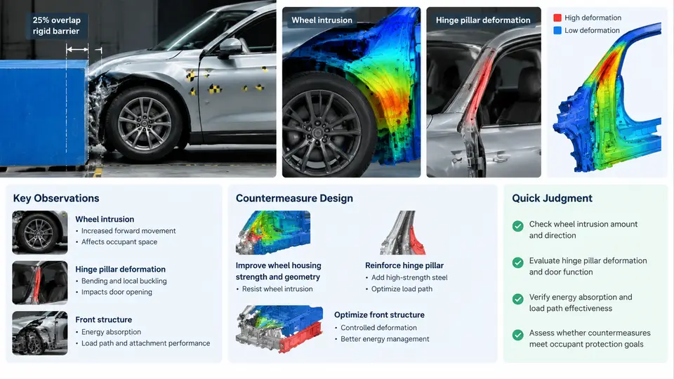
The small overlap frontal test is the most demanding frontal impact configuration in the IIHS evaluation suite. Unlike the moderate overlap test, which engages the longitudinal rails and allows the vehicle's primary crush structure to absorb energy, the small overlap test directs the impact force outboard of the rails, loading the wheel, suspension, and hinge pillar directly. This chapter examines the test setup, the specific deformation patterns that determine the rating, and the countermeasure strategies that vehicle developers use to manage this load path.
Test Configuration and Barrier Geometry
The test is conducted at 40 mph (64 km/h) with a rigid barrier that overlaps 25% of the vehicle's total width on the driver side. The barrier face is a rigid, non-deformable structure with a 150 mm radius rounded corner at the impact edge. The overlap is measured from the vehicle centerline to the outboard edge of the barrier, meaning the barrier covers the outer 25% of the vehicle width. For a typical vehicle with a 1,800 mm overall width, the barrier engages approximately 450 mm of the driver-side front structure.
The critical distinction from the moderate overlap test is the load path. In a 40% overlap test, the barrier contacts the longitudinal rail, which is designed to crush and absorb energy. In the small overlap test, the barrier misses the rail entirely and instead contacts the wheel, tire, suspension components, and the hinge pillar area. The vehicle's primary energy-absorbing structure is bypassed, and the occupant compartment must withstand the impact with minimal deformation.
- Impact speed: 40 mph (64 km/h)
- Overlap: 25% of vehicle width on driver side
- Barrier: rigid, with 150 mm radius rounded corner
- Primary contact points: wheel/tire, suspension, hinge pillar, rocker panel
- Rating criteria: occupant compartment intrusion, dummy injury measures, airbag performance
Wheel Intrusion and Suspension Loading
When the barrier strikes the front wheel, the wheel is forced rearward and inward. The suspension control arms, steering knuckle, and subframe are subjected to extreme loads that they were not designed to withstand in this direction. The wheel can be pushed into the footwell area, causing significant intrusion into the occupant compartment. In severe cases, the wheel can be displaced rearward by 300–500 mm, directly reducing the driver's survival space.
The suspension geometry plays a critical role in how the wheel behaves during impact. A MacPherson strut arrangement, common in compact and mid-size vehicles, allows the wheel to rotate around the strut tower, potentially directing the wheel upward and inward. A double-wishbone suspension may behave differently, with the upper and lower control arms absorbing and redirecting forces. The steering rack and tie rods can also be forced rearward, pushing the steering column into the driver's space.
Vehicle developers must consider the wheel's trajectory during the crash. If the wheel is pushed into the footwell, it can cause severe lower-leg and foot injuries. If it is pushed into the door and hinge pillar, it can compromise the door opening and increase the risk of occupant ejection. The goal is to manage the wheel's path so that it is directed away from the occupant compartment, typically by allowing it to be pushed outward or downward.
Hinge Pillar Deformation
The hinge pillar is the vertical structural member that connects the A-pillar to the rocker panel and supports the front door hinges. In a small overlap impact, the hinge pillar is subjected to bending and shear forces that can cause it to deform inward and rearward. This deformation directly reduces the driver's survival space and can cause the door to open or the dashboard to intrude into the occupant compartment.
IIHS measures hinge pillar deformation at specific points and compares the post-crash position to the pre-crash position. The intrusion is typically measured in millimeters, with ratings based on the maximum intrusion into the occupant compartment. A hinge pillar intrusion of less than 100 mm is generally considered good, while intrusion exceeding 200 mm is likely to result in a poor rating. The deformation pattern is also important: a hinge pillar that bends smoothly may be less dangerous than one that fractures or separates from the rocker panel.
The hinge pillar's connection to the rocker panel and the A-pillar is critical. If the hinge pillar separates from the rocker panel, the entire door opening can distort, potentially trapping the occupant or allowing the door to open during the crash. Vehicle developers often reinforce these joints with additional welds, gussets, or high-strength steel reinforcements.
Countermeasure Design Strategies
Vehicle developers have several countermeasure strategies to manage small overlap impacts. The most common approach is to add a wheel deflector or wheel blocker — a structural element that redirects the wheel outward or downward during impact, preventing it from being pushed into the footwell. This can be a simple steel bracket attached to the subframe or a more complex structure integrated into the front-end module.
Another strategy is to reinforce the hinge pillar and its connections to the rocker panel and A-pillar. This can be achieved through the use of high-strength steel, additional gussets, or structural adhesives. The goal is to maintain the integrity of the door opening and prevent the hinge pillar from separating from the rocker panel. Some manufacturers use a continuous closed-section design for the hinge pillar, which provides better bending resistance than an open-section design.
A third strategy is to create an additional load path that directs impact forces into the rocker panel and floor structure. This can be achieved by adding a subframe extension or a lower load path that engages the barrier earlier in the impact. By distributing the load over a larger area, the intrusion into the occupant compartment can be reduced.
Rating Criteria and Verification
IIHS rates small overlap performance based on three primary factors: occupant compartment intrusion, dummy injury measures, and airbag performance. The intrusion is measured at multiple points, including the hinge pillar, rocker panel, and footwell. The dummy injury measures include head, neck, chest, and lower leg responses. Airbag performance is evaluated based on whether the airbags deployed correctly and whether the dummy's head contacted the airbag or the vehicle interior.
To achieve a Good rating, the vehicle must maintain occupant compartment intrusion below specified thresholds, keep dummy injury measures within acceptable limits, and demonstrate proper airbag deployment. A vehicle that meets these criteria in the small overlap test is considered to have robust frontal crash protection.
Vehicle developers typically verify small overlap performance through a combination of finite element analysis (FEA) and physical crash testing. FEA simulations allow engineers to evaluate multiple design iterations quickly, while physical testing provides the final validation. The simulation model must accurately represent the wheel, suspension, and body structure, including the material properties and failure modes of each component.
Practical Development Workflow
When developing a vehicle for small overlap performance, engineers typically follow a structured workflow. First, they establish a baseline model and run a simulation of the small overlap test to identify the primary deformation modes and intrusion points. Second, they evaluate potential countermeasures through simulation, comparing the effectiveness of different wheel deflector designs, hinge pillar reinforcements, and load path modifications. Third, they select the most promising countermeasure package and validate it through physical testing. Finally, they refine the design based on test results and repeat the process until the performance targets are met.
The key to successful small overlap development is early integration of crash performance into the vehicle architecture. Retrofitting countermeasures after the body structure is finalized is difficult and expensive. By considering small overlap performance during the initial design phase, engineers can incorporate the necessary load paths and reinforcements without compromising other vehicle attributes such as weight, packaging, or manufacturing feasibility.