1. Automotive seating system crash safety d
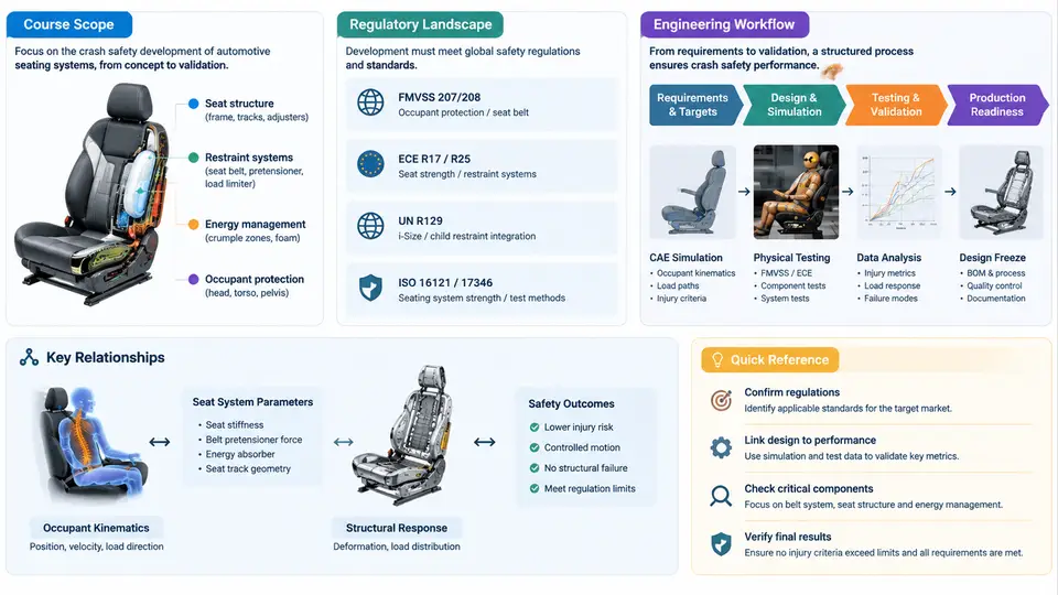
Automotive seating is not merely a comfort subsystem. In a crash, the seat is the primary structural interface between the occupant and the vehicle body: it must hold the occupant in a survivable posture, transfer belt and body loads into the floor and tunnel structure, and manage energy so that the occupant's spine, pelvis, and head are decelerated within tolerable limits. This course treats seating crash safety as a full development discipline — from regulatory and consumer-rating requirements, through CAE-driven concept design, hardware validation, and finally production sign-off. This opening chapter defines what the discipline covers, which regulations and rating programs govern it, and how a typical seat program actually flows from requirements to validated hardware.
1.1 What "Seating System Crash Safety" Actually Covers
The scope is broader than the seat frame alone. A complete seating crash-safety development scope includes:
- Seat structure: cushion frame, back frame, recliner mechanism, track/slide rails, risers, and mounting feet.
- Energy management: deformation zones, crush initiators, and controlled collapse of frame members.
- Restraint interfaces: seat belt anchorage points (both body-mounted and seat-integrated), buckle attachment, and belt routing over the seat.
- Occupant interfaces: head restraint geometry and stiffness, foam and trim behavior, and anti-submarining features.
- Adjacent systems: floor structure, tunnel, cross-car beams, and airbag interaction (side airbags routed through the seat).
Two structural philosophies dominate. In a body-mounted belt architecture, the belt loads go directly into the B-pillar and floor, and the seat mainly positions the occupant. In a seat-integrated belt (all-belts-to-seat) architecture, the seat frame itself carries belt loads, which dramatically raises the structural demand on the back frame, recliner, and risers. The choice of architecture is one of the earliest and most consequential decisions in the program, because it determines the load paths that every downstream analysis and test must verify.
1.2 The Regulatory and Rating Landscape
Seating crash safety is governed by a layered set of requirements: mandatory regulations, consumer rating programs, and internal OEM standards. The table below summarizes the most relevant ones for a global seat program.
| Requirement | Region / Program | Primary Focus | Typical Loading |
|---|---|---|---|
| FMVSS 207 | USA (mandatory) | Seat and seat anchorage strength | Static, 20× seat weight moment |
| FMVSS 202a | USA (mandatory) | Head restraint geometry and strength | Static + dynamic whiplash |
| FMVSS 225 | USA (mandatory) | Child restraint anchorage (LATCH) | Static pull |
| ECE R17 / R14 | Europe (mandatory) | Seat strength and belt anchorage | Static, defined force levels |
| ECE R25 | Europe (mandatory) | Head restraint | Static geometry and energy |
| GB 15083 / GB 11550 | China (mandatory) | Seat strength, head restraint | Static, harmonized with ECE |
| Euro NCAP / C-NCAP | Consumer rating | Whiplash, frontal, side, far-side | Sled and full-vehicle dynamic |
| IIHS | USA rating | Rear whiplash, moderate overlap | Sled and full-vehicle dynamic |
Two distinctions matter in practice. First, static requirements (FMVSS 207, ECE R17) apply a defined force or moment and check that the seat and its anchorage survive without exceeding a specified permanent deformation. Second, dynamic requirements (FMVSS 202a, Euro NCAP whiplash, sled tests) apply an acceleration pulse and evaluate occupant response — neck injury criteria (NIC), head-to-head restraint distance, and occupant kinematics. A seat that passes static strength can still fail a dynamic whiplash test, because the two load cases exercise different failure modes: static tests probe anchorage and frame yield, while dynamic tests probe head restraint proximity, foam stiffness, and recliner behavior under rapid loading.
1.3 The Engineering Workflow: From Requirements to Validated Hardware
A seat crash-safety program follows a V-model logic, but the practical workflow is iterative. The figure below shows the core development loop, from requirement definition through CAE, design iteration, hardware testing, and sign-off.
The workflow is not strictly linear. In practice, CAE and design iteration cycle several times before hardware is cut, and correlation results frequently send the program back to the concept stage. The red dashed feedback path in the figure is the norm, not the exception.
1.4 A Concrete Example: Seat-Integrated Belt Back Frame Load Path
To make the workflow tangible, consider a seat-integrated belt (all-belts-to-seat) front seat. The belt anchorage is on the seat back frame, so a frontal crash belt load of roughly 15–20 kN must travel from the belt anchor, through the back frame, into the recliner, down the cushion frame, through the track and risers, and finally into the floor. Each interface is a potential failure point.
A typical CAE check proceeds as follows. The back frame is modeled with shell elements for the stamped steel members and solid elements for the recliner core. A belt pull is applied at the anchor point at the regulation-specified angle. The analyst monitors three quantities: maximum von Mises stress in the back frame side members, relative rotation at the recliner pivot, and permanent deformation at the riser-to-floor mounting points. If the recliner rotation exceeds the allowable limit — often a few degrees — the design must be revised, typically by increasing the recliner core size or adding a reinforcement plate at the pivot. This is exactly the kind of iteration the feedback loop represents.
1.5 How This Course Is Organized
The remaining chapters follow the workflow above. Early chapters cover regulatory detail and load-case definition. The middle section develops CAE methods, material modeling, and design levers for frames, recliners, tracks, and head restraints. Later chapters address hardware testing, correlation, and production sign-off. Throughout, the emphasis is on the decisions an engineer actually makes: which load path to choose, which parameter to tune, how to read a CAE result, and when a test result means the design is ready or not.
By the end of this course, you should be able to take a seat concept, identify the governing crash load cases, build and interpret a CAE model, propose design changes that meet both static and dynamic targets, and plan the hardware validation that confirms the design before production release.