1. Rollover safety engineering overview
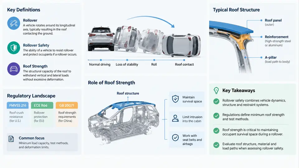
Rollover is one of the least frequent crash modes on the road, yet it accounts for a disproportionately large share of serious and fatal injuries. In the United States, rollovers represent roughly 2–3% of all police-reported crashes but are associated with approximately 20–30% of occupant fatalities in light passenger vehicles. This asymmetry is the reason rollover safety has evolved into a dedicated engineering discipline rather than a footnote within frontal and side impact design. This chapter establishes the vocabulary, the regulatory framework, and the physical rationale that connects roof strength to occupant survival.
What Counts as a Rollover
In crash engineering, a rollover is an event in which a vehicle rotates about its longitudinal axis by 90° or more, such that the roof or side plane contacts the ground. This distinguishes rollover from roll motion (suspension-level body lean) and from pitch (rotation about the lateral axis, as in a forward pitch-over). Two broad categories are recognized:
- Tripped rollover — the vehicle is laterally sliding and strikes a curb, soft soil, guardrail, or other tripping mechanism that converts lateral velocity into rotational momentum. Tripped events dominate real-world rollovers and typically produce fewer than two complete rolls.
- Untripped (maneuver-induced) rollover — the vehicle reaches a lateral acceleration high enough that the inside tires lift off the ground without an external tripping obstacle. This is the regime that the static stability factor (SSF) and the fishhook maneuver are designed to characterize.
The static stability factor is defined as SSF = T / (2H), where T is the track width and H is the height of the center of gravity (CG) above ground. A passenger car with T = 1.55 m and H = 0.55 m yields SSF ≈ 1.41; a tall SUV with T = 1.60 m and H = 0.75 m yields SSF ≈ 1.07. Lower SSF correlates with higher untripped rollover propensity, which is why NHTSA publishes a rollover resistance rating derived from SSF and a dynamic maneuver test.
The Regulatory Landscape
Roof strength regulation is anchored by FMVSS 216 (Federal Motor Vehicle Safety Standard 216, "Roof Crush Resistance") in the United States and by UN Regulation No. 94/ECE R94 and the newer UN GTR No. 9 harmonized requirements internationally. FMVSS 216 was significantly upgraded in 2009 (often called "FMVSS 216a") to extend coverage from a single-sided quasi-static plate test to a two-sided test and to raise the force requirement.
| Standard | Test Type | Force Requirement | Applicability |
|---|---|---|---|
| FMVSS 216 (pre-2009) | Single-side quasi-static plate | 1.5 × vehicle weight (up to 5,000 lb) | Passenger cars, light trucks |
| FMVSS 216a (2009+) | Two-sided quasi-static plate | 3.0 × vehicle weight (up to 6,000 lb) | Vehicles ≤ 6,000 lb GVWR |
| UN GTR No. 9 | Quasi-static or dynamic | Harmonized force/displacement envelope | International signatories |
The key engineering implication of FMVSS 216a is that the roof must withstand a force equal to three times the vehicle's unloaded weight applied through a rigid plate angled at 5° roll and 25° pitch, with the plate displacing no more than 127 mm (5 inches) before the force is reached. This is a quasi-static test, meaning inertial effects are not directly simulated; the standard assumes that a sufficiently strong roof in quasi-static loading will also perform adequately in the dynamic rollover event.
Why Roof Strength Matters for Occupant Protection
During a rollover, the roof is the primary load path between the ground and the occupant compartment. If the roof crushes inward, the survival space — the volume of the occupant compartment that must remain intact to prevent head and neck contact with the roof or ground — is compromised. Roof crush is strongly correlated with head and spinal injuries, particularly when the occupant is partially or fully ejected.
Three mechanisms link roof strength to injury outcomes:
- Survival space preservation. A stronger roof resists intrusion, maintaining the gap between the occupant's head and the roof interior. FMVSS 216a's 127 mm limit is a proxy for this space.
- Restraint coupling. Seat belts and side curtain airbags are effective only if the occupant remains in the seat. A roof that deforms excessively can pull the seat belt geometry out of position or allow the occupant to slip out from under the belt (submarining).
- Ejection prevention. Ejection is the single strongest predictor of fatal injury in rollovers. A rigid roof structure supports the door frames, glazing, and side curtains that keep the occupant inside.
It is important to note that roof strength alone is not sufficient. The restraint system (seat belts with pretensioners and load limiters, side curtain airbags with rollover deployment logic), the seat structure, and the door latch and hinge integrity all contribute. Roof strength is the structural foundation upon which these systems operate.
From Regulation to Design: A Practical Workflow
Meeting FMVSS 216a is not a matter of simply adding material. The engineer must balance roof strength against mass, cost, manufacturing feasibility, and other crash modes. A typical development sequence for a new roof structure looks like this:
- Establish the target. Calculate the required force: 3.0 × unloaded vehicle weight. For a 2,200 kg vehicle, that is ≈ 64.7 kN. Add a safety margin (typically 10–15%) for production variation and test scatter.
- Define the load path. Identify how force applied at the roof rail will travel through the B-pillar, A-pillar, C-pillar, and rocker into the floor. The goal is to avoid a single weak link that localizes deformation.
- Select materials and gauges. High-strength steel (HSS) and ultra-high-strength steel (UHSS) are common in pillars and roof rails. A typical B-pillar might use 1.4–1.8 mm UHSS with a yield strength of 800–1,200 MPa, while the roof rail may use 1.0–1.4 mm HSS at 500–700 MPa.
- Run CAE simulation. A nonlinear finite element model applies the FMVSS 216a plate at the specified angle and displacement rate. The engineer monitors force–displacement curves and identifies where the structure yields first.
- Iterate and validate. Physical tests on a body-in-white confirm the simulation. If the roof fails, the engineer adds reinforcements, adjusts gauges, or changes the load path — then re-tests.
Key Definitions Summary
| Term | Definition | Engineering Relevance |
|---|---|---|
| Rollover | Vehicle rotation ≥ 90° about longitudinal axis with roof/side ground contact | Defines the crash mode; distinguishes from roll motion and pitch |
| SSF | Static Stability Factor = T / (2H) | Predicts untripped rollover propensity; basis for NHTSA rating |
| FMVSS 216a | Two-sided quasi-static roof crush test at 3.0× vehicle weight | Primary U.S. regulatory requirement for roof strength |
| Survival space | Occupant compartment volume that must remain intact during rollover | Directly linked to head/neck injury risk; 127 mm limit is a proxy |
| Ejection | Occupant being partially or fully expelled from the vehicle | Strongest predictor of fatal injury in rollovers |
With these definitions and the regulatory baseline established, the next step is to examine the specific structural members — roof rails, headers, pillars, and their joints — that carry the rollover load. The chapters that follow will move from this overview into material selection, CAE methodology, physical test setup, and failure analysis, building a complete engineering picture of how roof strength is designed, verified, and improved.