4. Occupant kinematics in low-to-moderate s
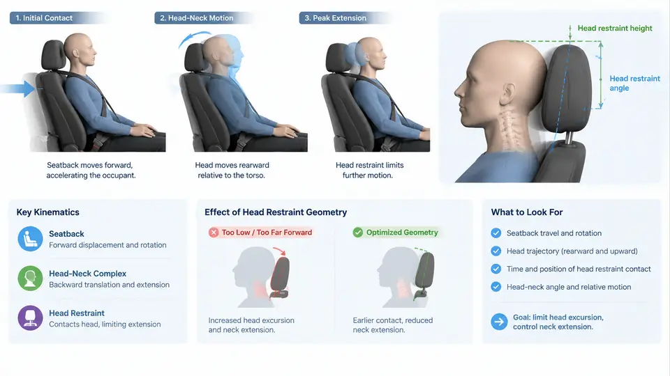
In a rear impact, the struck vehicle is accelerated forward while the occupant initially remains at rest due to inertia. The seat, through its cushion and seatback, becomes the primary interface that pushes the occupant forward. Because the seatback contacts the torso before the head restraint contacts the head, the upper torso is loaded first, and the head lags behind. This sequence — torso forward, head relatively stationary — produces the characteristic S-shaped curvature of the cervical spine and is the mechanical origin of whiplash-type injury. Understanding this sequence, and how head restraint geometry modifies it, is the foundation of all rear-impact protection design.
Reference Frame and Sign Convention
Throughout this chapter, the vehicle coordinate system follows ISO 8855: x is positive forward (direction of travel), y is positive to the left, and z is positive upward. In a rear impact, the bullet vehicle strikes from behind, so the struck vehicle accelerates in the +x direction. The occupant's head, initially at rest in the ground frame, therefore moves in the −x direction relative to the seat during the early phase. All "forward/backward" descriptions below refer to motion relative to the seat and vehicle, not the ground.
The Three-Phase Kinematic Sequence
At low-to-moderate severity (Δv roughly 8–25 km/h), the occupant response unfolds in three overlapping phases:
- Ramp-up / torso loading (0–50 ms). The seatback cushion compresses and the seat structure begins to push the torso forward. The pelvis and lower torso are engaged first. The head, still nearly stationary in space, is left behind, so the neck extends (head rotates rearward relative to the torso).
- Retraction and S-curve (50–120 ms). The lower cervical spine is pulled forward while the upper cervical spine remains extended. This opposing curvature — lower flexion, upper extension — is the S-shape. It concentrates shear and tensile loading in the facet joints and posterior ligaments of the mid-cervical spine.
- Rebound / head restraint contact (100–250 ms). The head either contacts the head restraint (limiting rearward excursion) or continues rearward until soft tissue and joint limits arrest it. The torso then decelerates and the head rebounds forward, producing a second, smaller flexion excursion.
The magnitude of the S-curve and the peak head-to-torso relative rotation (often called head rotation or neck extension angle) are the key kinematic metrics correlated with injury risk. Reducing the gap between the head and the restraint, and raising the restraint, directly reduces both.
Head Restraint Geometry: Backset and Height
Two geometric parameters dominate head restraint effectiveness:
- Backset — the horizontal distance from the back of the head to the front face of the head restraint, measured with the head in its normal seated posture. Backset is the single most influential parameter. A backset of 0–50 mm allows early head contact and limits extension; a backset above 100 mm permits large head excursion before contact.
- Height — the vertical position of the restraint's top edge relative to the head's center of gravity (CG). For effective support, the top of the restraint should be at or above the head CG. A restraint whose top edge is below the head CG allows the head to rotate over the top of the restraint, a condition called ramping or submarining of the head.
Regulatory and rating programs quantify these. ECE R17 and FMVSS 202a define geometric zones; the IIHS and Euro NCAP rate restraints as good, acceptable, marginal, or poor based on backset and height measured with a standardized procedure (the HRMD — Head Restraint Measuring Device). A restraint rated "good" typically has backset ≤ 70 mm and top edge at or above head CG.
Seatback Interaction and the Role of Stiffness
The seatback is not a rigid plate. Its stiffness profile determines how quickly the torso is accelerated and how much it rotates rearward. A very stiff seatback transmits energy quickly, reducing the time available for the head to be captured by the restraint. A compliant seatback allows the torso to sink in, which can reduce peak acceleration but may increase the relative head–torso rotation if the head is not supported. Modern "whiplash-optimized" seats use a tuned recliner and a yielding upper crossmember that absorb energy while keeping the head close to the restraint. Some designs (e.g., active head restraints) use a linkage that pushes the restraint forward and upward when the occupant's pelvis loads the seatback, reducing backset dynamically during the impact.
Kinematic Visualization
The figure below shows the three-phase sequence and how backset and height change the head trajectory. The left panel is a well-adjusted restraint (low backset, high top edge); the right panel is a poorly adjusted one (large backset, low top edge). Note the larger head excursion and the over-the-top rotation in the right panel.
Practical Adjustment and Verification
Because backset and height are adjustable in most vehicles, the occupant's own adjustment is a major determinant of protection. A reproducible procedure to set and verify a restraint is:
- Sit in the normal driving posture with the pelvis against the seatback and the back against the cushion.
- Adjust the restraint so its top edge is at least level with the top of the head, ideally at or above the head's CG (roughly the level of the ears).
- Adjust the restraint forward (if adjustable) or move the seatback angle slightly more upright to reduce backset. Target backset ≤ 70 mm; ≤ 50 mm is better.
- Verify by placing a hand behind the head: the gap should be small enough that the head contacts the restraint with minimal rearward movement.
Typical Failure Symptoms and Troubleshooting
| Symptom | Likely cause | Corrective action |
|---|---|---|
| Head rotates over the top of the restraint | Restraint top edge below head CG | Raise restraint; reduce seatback recline |
| Large rearward head excursion before contact | Backset too large | Move restraint forward; adjust seatback angle; use active restraint |
| Occupant reports neck soreness after low-speed impact | Residual backset and/or low restraint height | Re-measure geometry; verify with HRMD; consider aftermarket adjustment |
| Restraint does not lock in raised position | Detent or locking mechanism wear | Inspect and replace restraint assembly |
The key engineering takeaway is that head restraint geometry — specifically backset and height — controls the head's rearward excursion and the severity of the S-curve. Seatback stiffness and recliner tuning shape the timing, but geometry sets the boundary condition. In the next chapter, we move from kinematics to the injury mechanisms these motions produce in the cervical spine.