4. Airbag system architecture
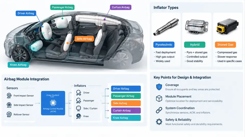
An airbag system is not a single device but a distributed restraint network coordinated by the Airbag Control Unit (ACU), often called the SDM (Sensing and Diagnostic Module). Each airbag location has a distinct purpose, deployment threshold, inflator technology, and integration constraint. Understanding the architecture means understanding which module fires under which crash mode, how the inflator generates gas, and how the module is mechanically and electrically integrated into the vehicle.
Positioning and Function of Each Airbag
The driver frontal airbag is mounted in the steering wheel hub and deploys rearward toward the driver's chest and head. Typical volume is 60–70 L for a US-market driver bag. The passenger frontal airbag sits in the instrument panel above the glovebox and is larger, typically 100–150 L, because it must cover a wider occupant envelope and a greater distance to the occupant. Passenger bags almost always use a tethered or dual-stage inflator to manage out-of-position (OOP) risk.
Side airbags (thorax/pelvis) are mounted in the outboard side of the front seat backrest. They deploy in side impacts to protect the torso and pelvis, with volumes around 12–20 L. Curtain airbags run along the roof rail from the A-pillar to the C-pillar and deploy downward like a curtain to protect the head in side impact and rollover. Curtain volume is typically 25–40 L per side. Knee airbags are mounted below the steering column or in the lower instrument panel; they deploy rearward to control femur loading and to keep the occupant positioned against the frontal bag, typically 10–15 L.
Inflator Types and Their Selection Logic
The inflator is the gas generator. Its type determines deployment timing, output profile, and packaging. The main families are:
- Pyrotechnic (solid propellant) — sodium azide or non-azide gas generant. Fast, compact, low cost. Common in driver and passenger frontal modules.
- Hybrid — a small pyrotechnic charge heats and releases compressed argon/helium from a pressure vessel. Used where a cooler, more controlled gas output is needed, e.g., some side and curtain modules.
- Stored gas — compressed gas only, no propellant combustion. Very clean and cool, used in some curtain and knee applications.
- Dual-stage / variable output — two initiators or a controllable vent. The ACU selects stage 1, stage 2, or both based on crash severity, belt status, and occupant classification.
Selection is driven by packaging space, required fill time (typically 20–40 ms to full inflation for frontal bags), gas temperature limits, and OOP performance. A curtain bag that must stay inflated for rollover (several seconds) uses a different inflator and fabric construction than a frontal bag that vents immediately.
Electrical Architecture and Firing Loop
Each airbag module contains a squib (initiator) with a nominal resistance of about 2 Ω. The ACU drives each squib through a dedicated firing loop with two independent lines (high-side and low-side) to prevent inadvertent deployment from a single short. The ACU continuously monitors loop resistance; a value outside roughly 1.5–3.5 Ω sets a diagnostic trouble code (DTC).
Crash sensing uses accelerometers in the ACU plus satellite sensors at the front and sides of the vehicle. The ACU runs a crash algorithm that classifies the event and decides which loops to fire. A simplified firing decision table for a frontal event looks like this:
| Condition | Driver bag | Passenger bag | Knee bag | Belt pretensioner |
|---|---|---|---|---|
| Low severity, belted | Stage 1 | Stage 1 | No fire | Fire |
| High severity, belted | Stage 1+2 | Stage 1+2 | Fire | Fire |
| High severity, unbelted | Stage 1+2 | Stage 1+2 | Fire | Fire |
| Passenger seat empty (OCS) | Stage 1+2 | Suppressed | Fire | Fire |
The Occupant Classification System (OCS) in the passenger seat uses pressure sensors and sometimes a camera to decide whether to suppress the passenger bag. This is a legal requirement in many markets and directly affects the firing table above.
Module Integration and Mechanical Constraints
Integration is where architecture meets the vehicle. The driver module must fit inside the steering wheel while leaving room for the horn, switches, and clock spring. The passenger module must open through a tear seam in the instrument panel; the seam geometry and the chute that guides the bag determine whether the bag deploys through the windshield or into the occupant. Curtain modules must be routed behind the headliner and above the door openings, with tethers that hold the bag in place during rollover.
Key integration checks include:
- Tear seam validation — the seam must open at the specified pressure and temperature without fragmenting.
- Deployment trajectory — the bag must not strike the occupant before full inflation in OOP tests.
- Harness routing — squib leads must be short, shielded, and strain-relieved to avoid chafing.
- Grounding and shielding — the firing loop must be isolated from chassis ground to prevent false deployment.
Practical Example: Verifying a Curtain Airbag Loop
Suppose a vehicle sets DTC B0012 (driver side curtain loop open). The diagnostic procedure is:
- Disconnect the battery and wait at least 3 minutes for capacitor discharge.
- Disconnect the curtain module connector and inspect for bent pins or corrosion.
- Measure loop resistance from the ACU connector to the module connector using a breakout box. Expected value: 1.8–2.4 Ω.
- If resistance is infinite, inspect the harness for a break. If resistance is below 1.5 Ω, inspect for a short between the two lines.
- Reconnect, clear the DTC, and cycle the ignition. If the code returns, replace the harness or the module as indicated.
This example shows how the electrical architecture, the diagnostic strategy, and the mechanical integration are inseparable in practice.
Key Takeaways for Integration Engineers
Architecture decisions cascade: the choice of inflator affects module volume, which affects packaging, which affects tear seam design, which affects OOP performance. The firing loop design affects harness routing and EMC strategy. The OCS affects the firing table and therefore the legal compliance of the passenger restraint. A well-integrated airbag system is one where these dependencies are documented, validated, and traceable from the ACU calibration back to the physical module in the vehicle.