1. Passive safety system landscape
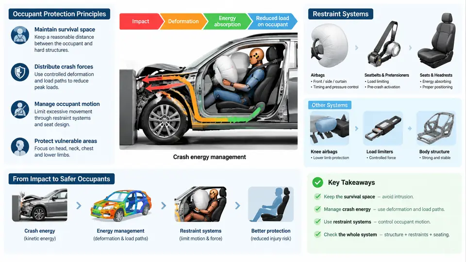
Passive safety refers to every vehicle function that mitigates injury after a collision has become unavoidable. Unlike active safety, which acts before impact through braking, steering, or stability control, passive safety operates during the crash event itself. Its design objective is straightforward to state and difficult to achieve: manage the kinetic energy of the collision so that the occupant experiences the lowest possible deceleration, over the longest possible time, with loads distributed across the strongest regions of the body.
This chapter establishes the conceptual foundation for the entire course. It defines the physical principles that govern occupant protection, explains how a vehicle body absorbs and redirects crash energy, and positions the restraint system as the final and most occupant-proximal layer of the safety chain.
1.1 The Physical Basis of Occupant Protection
Every crash is an energy problem. A vehicle of mass m travelling at velocity v carries kinetic energy E = ½mv². At 50 km/h (13.9 m/s), a 1,600 kg vehicle carries roughly 154 kJ. That energy cannot be destroyed; it can only be converted, primarily into deformation work, friction, and heat. The rate at which this conversion occurs determines the severity of the loads transmitted to the occupant.
Two relationships dominate passive safety design. The first is the impulse–momentum relation: the average force F acting over a crash duration Δt equals the change in momentum, F·Δt = m·Δv. For a fixed Δv, extending Δt reduces F proportionally. The second is the ride-down concept: if the occupant can be decelerated together with the vehicle's crushable structure rather than striking a rigid barrier, the occupant's deceleration is spread over the full crush stroke. A vehicle front end that crushes 600 mm instead of 200 mm can, in principle, reduce average occupant deceleration by a factor of three.
These principles explain why modern vehicles are deliberately designed to be soft where they must absorb energy and rigid where they must protect the occupant cell. They also explain why restraint systems must be tuned to the vehicle's deceleration pulse rather than treated as standalone devices.
1.2 Crash Energy Management in the Body Structure
Crash energy management is the discipline of directing collision forces along defined load paths and converting kinetic energy into controlled plastic deformation. A typical frontal structure divides into three functional zones:
- Crush zone (front end): longitudinal rails, bumper beam, crash boxes, and the subframe are designed to fold in a predictable accordion pattern. Their purpose is to absorb energy at a controlled force level, typically 150–400 kN for a passenger car, and to keep that force as constant as possible throughout the stroke.
- Compatibility zone (mid-structure): the firewall, floor tunnel, and rocker panels distribute residual loads into the floor and away from the occupant compartment. This zone also manages the interaction between the vehicle and the object struck, which is critical for compatibility between vehicles of different masses.
- Safety cell (occupant compartment): the A-pillars, B-pillars, roof rails, and door beams form a high-strength cage using hot-stamped boron steel with tensile strengths above 1,300 MPa. This cell must remain largely undeformed to preserve survival space and provide a stable reaction surface for the restraint system.
Load path continuity is the central engineering concern. A rail that terminates without transferring its load into the floor or rocker creates a stress concentration and unpredictable deformation. In practice, engineers verify load paths through finite element simulation and then confirm them with physical barrier tests — full-width rigid barrier, offset deformable barrier (ODB), and small overlap tests such as the IIHS 25% overlap.
1.3 The Restraint System as the Final Interface
The body structure manages the vehicle's energy. The restraint system manages the occupant's energy relative to that structure. It comprises seat belts with pretensioners and load limiters, airbags (frontal, side, curtain, knee, and far-side), seat structures, head restraints, and increasingly, active interventions such as reversible pretensioners and seat-belt-integrated airbags.
The seat belt remains the single most effective restraint device. A three-point belt couples the occupant's torso and pelvis to the seat and vehicle, ensuring that deceleration is transmitted through the skeletal structure rather than through soft tissue. Pretensioners remove belt slack within 10–20 ms of impact detection, and load limiters then allow controlled belt payout — typically 40–80 mm — to cap the force applied to the chest. This combination is what produces the characteristic plateau in occupant chest deceleration.
Airbags are supplementary, not primary. They distribute contact forces over a larger area and prevent the occupant from striking hard interior surfaces, but they are effective only when the occupant is correctly positioned and belted. An unbelted occupant can move forward before the airbag is fully inflated, which is why out-of-position (OOP) sensing and dual-stage inflators are now standard.
1.4 The Integrated Safety Chain
Passive safety is not a collection of independent components; it is a chain in which each link must function within its timing window. The figure below shows the sequence from impact detection through restraint deployment and the resulting occupant response.
The timeline is instructive. Impact detection occurs within 5–15 ms. Pretensioners fire at roughly 10–20 ms. Frontal airbags begin deployment at 15–30 ms and are fully inflated by 40–60 ms. Load limiters become active as the occupant loads the belt, typically from 30 ms onward. The occupant's forward excursion peaks between 80 and 120 ms. Every one of these events must occur in the correct order and within its window; a late airbag or an early load limiter can be as harmful as a missing component.
1.5 Regulatory and Rating Context
Passive safety development is driven by two parallel forces: regulation and consumer rating. Regulation establishes minimum performance — FMVSS 208 in the United States, ECE R94/R95 in Europe, and GB 11551 in China. Consumer programs such as Euro NCAP, C-NCAP, and IIHS go further, introducing offset deformable barrier tests, mobile progressive deformable barrier tests, and far-side occupant protection. These programs increasingly evaluate the interaction between structure and restraint, not just the presence of equipment.
For the development engineer, this means that restraint calibration cannot be separated from body-in-white design. The airbag's inflation pressure, the belt's load-limiting force, and the seat's energy absorption must all be tuned against the measured deceleration pulse of the specific vehicle structure.
1.6 Key Takeaways
- Passive safety manages kinetic energy after impact; its goal is to minimize occupant deceleration by extending crash duration and distributing loads.
- Crash energy management divides the vehicle into crush, compatibility, and safety-cell zones, each with a defined force and deformation role.
- The restraint system is the final interface between the decelerating vehicle and the occupant; seat belts are primary, airbags supplementary.
- Timing is critical: detection, pretensioning, airbag deployment, and load limiting must occur in a coordinated sequence within the first 120 ms.
- Regulation and consumer ratings increasingly assess the integrated performance of structure and restraint, not isolated components.