4. Free-motion headform and guided headform
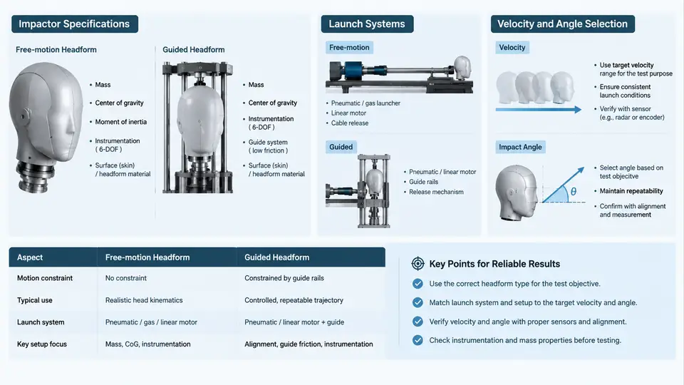
Head impact testing in automotive interiors relies on two fundamentally different impactor delivery philosophies: the free-motion headform (FMH) and the guided headform. Both use a surrogate headform instrumented with a triaxial accelerometer at its center of gravity, but they differ in how the headform is accelerated, how its trajectory is constrained, and therefore which injury mechanisms they can credibly reproduce. Selecting the wrong method, or mis-parameterizing velocity and impact angle, produces data that looks valid but does not represent the occupant loading you intended to study.
Impactor Specifications
The two methods share a common impactor family defined by mass, geometry, and instrumentation. The most widely referenced is the 4.54 kg (10 lb) spherical headform with a 165 mm diameter, specified in FMVSS 201 and ECE R21 for upper interior head impact. A smaller 3.5 kg, 165 mm headform appears in pedestrian and some interior side-impact protocols, while a 2.5 kg variant is used where lower energy is required. The headform skin is a vinyl or PVC covering over an aluminum shell; skin hardness affects contact duration and must be controlled, since a stiffer skin shortens the pulse and raises peak acceleration for the same impact energy.
Instrumentation is a single triaxial accelerometer (or a small array) mounted at the headform center of gravity, sampled at a minimum of 10 kHz with an anti-alias filter typically set to 1650 Hz per SAE J211/1. The measured resultant acceleration ar is converted to HIC using the standard 36 ms or 15 ms window. Because HIC is dominated by the peak and duration of the pulse, the launch system's ability to deliver a repeatable velocity and a clean, non-ringing impact is as important as the headform itself.
Free-Motion Headform: Launch and Trajectory
In the free-motion method, the headform is accelerated by a pneumatic launcher (a compressed-air cannon) and then released; from the muzzle onward it travels ballistically with no mechanical constraint. The launcher consists of a pressure reservoir, a fast-acting solenoid or burst-diaphragm valve, a barrel, and a sabot or carrier that separates from the headform at the muzzle. Velocity is set by reservoir pressure and verified by a pair of light gates or a high-speed camera immediately before impact.
The critical characteristic of FMH is that the headform's orientation and trajectory are determined entirely by the launch vector and gravity. This makes it the appropriate choice when the real-world event involves a head that is already moving freely — for example, a rear-seat occupant's head striking a seatback-mounted display, or a head rebounding into a B-pillar. The trade-off is reduced repeatability: small variations in sabot separation, muzzle blast, and gravity drop over the free-flight distance introduce scatter in both impact location and angle.
Guided Headform: Constrained Trajectory
The guided headform is mounted on a linear guide — typically a rail, a pendulum arm, or a sled carriage — that constrains the headform to a single degree of freedom along a defined axis. The most common laboratory implementation is the pendulum, where the headform is rigidly attached to an arm of known length and released from a calculated drop height. The sled-based variant accelerates the headform along a rail using a pneumatic or servo-hydraulic actuator.
Guidance buys repeatability and precise angle control at the cost of realism: the constraint adds inertia and friction, and the headform cannot rotate freely after impact. Guided methods are therefore preferred for component qualification and for studying a single, well-defined impact condition — for example, evaluating whether a specific trim substrate meets a HIC target at a fixed 50° impact angle. They are less suitable for reproducing complex, multi-contact occupant kinematics.
Velocity and Angle Selection
Velocity and impact angle are the two parameters that most strongly determine the resulting HIC, and both must be justified against the occupant scenario being represented, not chosen for convenience.
Velocity. For upper interior head impact, FMVSS 201 specifies a free-motion headform at 24.1 km/h (15 mph) for the mandatory target set, representing a 90th-percentile adult head in a frontal or lateral collision. Component-level guided tests frequently use lower velocities — 15 to 20 km/h — to isolate material behavior without saturating the structure. As a rule, HIC scales approximately with velocity raised to the 2.5 power for a given stiffness, so a 20% velocity error produces roughly a 60% HIC error. Velocity must therefore be measured, not assumed from reservoir pressure.
Angle. The impact angle is defined as the angle between the headform velocity vector and the surface normal at the contact point. A normal (0°) impact maximizes energy transfer and produces the highest HIC; oblique impacts slide and reduce peak acceleration. FMVSS 201 requires the headform to be aimed along the direction of travel of a 50th-percentile male head, which in practice yields impact angles between roughly 30° and 60° from the surface normal depending on target location. For guided tests, the angle is set by the fixture geometry and must be reported explicitly, because a 10° change in incidence can shift HIC by 15–25% on stiff trim.
Practical Selection and Verification
Choose FMH when the research question involves a freely moving head and realistic post-impact kinematics; choose the guided method when you need a repeatable, angle-controlled comparison between materials or designs. In either case, verify the setup before trusting the data:
- Velocity calibration: fire three shots at the target pressure and confirm the light-gate velocity is within ±2% of the intended value. If scatter exceeds this, inspect the sabot for wear and the valve for slow opening.
- Angle verification: for FMH, use a high-speed camera to confirm the actual incidence angle at contact; for guided tests, measure the fixture angle with a digital protractor rather than trusting the drawing.
- Pulse check: a clean impact produces a single, smooth acceleration pulse. Ringing or a double peak usually indicates headform–fixture contact, a loose accelerometer mount, or a sabot striking the target.
- HIC sanity check: compare the measured HIC against the expected range for the material class. A HIC far below expectation often means the headform missed the intended target or the accelerometer cable restrained the motion.
In practice, a well-run program uses both methods in sequence: guided tests to screen and rank candidate designs under controlled conditions, then free-motion tests on the best candidates to confirm performance under realistic occupant kinematics. Documenting the impactor mass, skin condition, launch pressure, measured velocity, measured angle, and filter class for every shot is what makes the results reproducible and defensible.