4. Material selection for frontal crash str
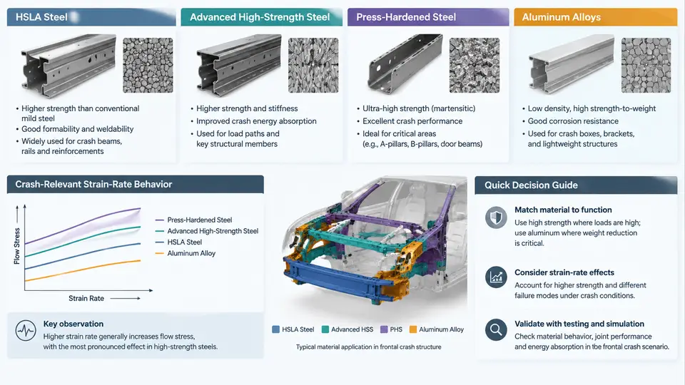
Frontal crash structures are not designed from a single material. A modern body-in-white (BIW) front end is a graded assembly in which each zone is matched to a dominant loading mode: bending collapse in the front bumper beam, progressive axial folding in the crash boxes, mixed bending–axial crush in the front rails, and high-magnitude, low-strain bending at the A-pillar and hinge pillar. Material selection therefore follows the load path, not the part list. This chapter explains how HSLA, advanced high-strength steel (AHSS), press-hardened steel (PHS), and aluminum alloys are chosen, and why strain-rate behavior is a first-order design variable rather than a correction factor.
Strength, Ductility, and the Formability–Crash Trade-off
The governing material metrics for crash structures are yield strength (Rp0.2), ultimate tensile strength (Rm), total elongation (A80), the strain-hardening exponent n, and the strain-rate sensitivity m. A common misconception is that higher strength always improves crash performance. In axial crush, energy absorption per unit mass depends on the product of a stable mean crush force and the crush distance. If a material is too strong and too brittle, the rail fractures at the first fold, the crush force collapses, and the remaining structure is bypassed. The practical selection rule is: choose the lowest strength grade that prevents buckling or intrusion in the target mode, then add ductility margin for the forming route.
HSLA steels (e.g., HSLA 340/440, HSLA 550) offer Rm of roughly 440–600 MPa with A80 above 20%. They are inexpensive, weldable, and ideal for crash boxes and bumper beams where stable folding matters more than peak strength. AHSS grades — dual-phase (DP600–DP980), complex-phase (CP800–CP1000), and transformation-induced plasticity (TRIP780–TRIP980) — provide higher strength with retained elongation. DP980 typically shows Rm ≈ 980 MPa with A80 ≈ 10–14%, which is sufficient for front rails if bend radii and edge quality are controlled. PHS (22MnB5, hot-stamped and quenched) reaches Rm ≈ 1500 MPa with A80 ≈ 5–7%; it is used where intrusion resistance dominates and crush energy absorption is secondary — A-pillar, B-pillar, roof rail, and door ring reinforcements.
Aluminum Alloys in the Front End
Aluminum front structures typically use 6xxx-series extrusions (e.g., 6060, 6082) for crash boxes and rails, and 5xxx/6xxx sheet for closures. Extruded 6082-T6 reaches Rp0.2 ≈ 310 MPa with 8–12% elongation; its specific energy absorption in axial crush is competitive with HSLA because density is one-third that of steel. The critical difference is joining and failure mode: aluminum crush initiators must be designed for the lower ductility and the absence of the bake-hardening benefit that steel enjoys after paint. Aluminum also shows a weaker strain-rate sensitivity than BCC steels, so the quasi-static crush result transfers more directly to dynamic testing — but the fracture strain is lower, so trigger geometry is decisive.
Strain-Rate Behavior: Why It Changes the Answer
Frontal crash events load material at strain rates of 101–103 s−1, versus 10−3–10−1 s−1 in a tensile test. Body-centered cubic steels exhibit positive strain-rate sensitivity: yield strength rises with rate, typically 10–30% for HSLA and DP grades at 103 s−1, and up to 40–50% for some PHS conditions. Face-centered cubic aluminum is much less rate-sensitive, often only 5–15%. The consequence is that a steel rail designed from quasi-static data will over-predict crush distance and under-predict peak force; the reverse error appears if rate effects are ignored in the intrusion calculation.
Rate sensitivity is captured by the Cowper–Symonds relation, σd/σs = 1 + (ε̇/D)1/p, or by a Johnson–Cook-type model. For a DP780 rail, representative parameters are D ≈ 4×10⁵ s−1 and p ≈ 4; at ε̇ = 1000 s−1 this gives a dynamic-to-static yield ratio near 1.2. That 20% is not a rounding error — it directly shifts the peak deceleration and the fold pattern.
Selection Workflow and a Worked Example
Consider a front rail for a C-segment SUV targeting a 64 km/h offset deformable barrier (ODB) test. The rail must absorb approximately 35 kJ over 350 mm of crush while limiting intrusion at the firewall to 120 mm. The workflow is:
- Define the mode. The rail is a mixed axial–bending member; the crash box ahead of it must fold axially.
- Screen by strength and elongation. DP780 or DP980 with A80 ≥ 12% is a candidate; PHS is excluded from the crush zone because A80 ≈ 6% risks fracture at the fold.
- Check rate-dependent mean crush force. Using a simplified mean force Fm ≈ 1.3·σd·t1.5·b0.5 for a square section, with t = 1.8 mm, b = 90 mm, and σd = 1.2 × 780 MPa, gives Fm ≈ 95 kN. Over 350 mm this yields about 33 kJ — close to the 35 kJ target, so thickness is increased to 2.0 mm.
- Assign PHS to the intrusion path. The hinge pillar and A-pillar reinforcement use 22MnB5 at 1.4 mm, where bending stiffness and intrusion resistance dominate and crush energy is not required.
- Verify with dynamic testing. A drop-tower or sled test at 10–15 m/s confirms the fold pattern and the absence of fracture.
The table below summarizes the selection logic across the front-end zones.
| Zone | Dominant mode | Typical material | Key property driver |
|---|---|---|---|
| Bumper beam | Bending | HSLA 550 / DP600 | Rm, bend ductility |
| Crash box | Axial folding | HSLA 440 / DP780 | A80, stable fold |
| Front rail | Mixed axial–bending | DP780 / DP980 | Rate-dependent Fm |
| Hinge pillar / A-pillar | Bending, intrusion | PHS 22MnB5 | Rm, stiffness |
| Aluminum front end | Axial crush | 6082-T6 extrusion | Specific energy, fracture strain |
Joining and Manufacturing Constraints
Material selection cannot be separated from joining. PHS cannot be spot-welded to aluminum without a transition; self-piercing rivets and structural adhesives are used for aluminum-to-steel joints, and their rate-dependent behavior must be characterized separately. DP980 has a narrow weld lobe, so weld schedule development is part of the material decision. Springback in DP and PHS grades requires compensation in the die, and edge cracking in PHS is controlled by laser trimming rather than mechanical shearing.
Verification and Data Requirements
For each candidate material, the validation plan should include quasi-static tensile tests at 10−3 s−1, intermediate-rate tests at 1–10 s−1, and high-rate tests at 102–103 s−1 using a split Hopkinson pressure bar or servo-hydraulic high-rate frame. The output is a rate-dependent true stress–strain curve that feeds the crash model. Component-level validation then uses drop-tower axial crush and three-point bending to confirm the fold pattern and force–displacement response. The acceptance criteria are: mean crush force within ±10% of target, no fracture before 80% of the intended crush distance, and peak force below the occupant-load limit.
The figure maps the front-end load path to material grades and shows the relative strain-rate amplification that must be applied in the crash model. The key takeaway is that material selection is a load-path decision: HSLA and DP grades carry the crush energy, PHS carries the intrusion resistance, and aluminum offers a mass-efficient alternative where fracture strain and joining are managed explicitly. Strain-rate data is not optional — it is the bridge between the tensile test and the sled test.