1. Course overview
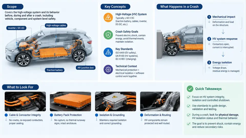
An electric vehicle involved in a collision is no longer only a mechanical and restraint-engineering problem. It is simultaneously an electrical problem, a chemical problem, and a thermal problem. A 400 V or 800 V traction battery pack can deliver hundreds of kilowatts during normal operation, and after a crash it may still hold dangerous voltage, may have deformed cells, and may be undergoing invisible electrochemical reactions. High-voltage crash safety is the engineering discipline that ensures these hazards are controlled before, during, and after an impact event.
This course treats high-voltage crash safety as a system-level property, not a single component feature. It spans battery pack design, contactor and fuse behavior, insulation monitoring, crash sensing, pyrotechnic disconnection, service procedures, and post-crash rescue operations. The goal of this first chapter is to establish the vocabulary, the physical boundaries, and the regulatory context that the remaining 29 chapters build upon.
1.1 What "High Voltage" Means in an EV Context
In automotive practice, a circuit is classified as high voltage when its nominal operating voltage exceeds the limits defined by the applicable standard. Under ISO 6469-3 and UN ECE R100, the commonly applied threshold is 60 V DC or 30 V AC (RMS). Anything above this is a Class B voltage system and requires protection against direct and indirect contact.
Typical EV traction architectures fall into two voltage classes:
| Class | Nominal pack voltage | Typical vehicles | Key crash-safety implication |
|---|---|---|---|
| 400 V class | 350–450 V DC | Most first-generation BEVs, PHEVs | Lower arc-flash energy, thicker cables for same power |
| 800 V class | 650–900 V DC | Modern fast-charging platforms | Higher insulation stress, faster disconnection required |
The distinction matters because insulation coordination, creepage and clearance distances, and the energy available during a fault scale with voltage. An 800 V pack can sustain a more energetic arc across a damaged connector than a 400 V pack under identical mechanical damage.
1.2 The Three Crash-Safety Objectives
Every design decision in this course can be traced back to three objectives that must be satisfied simultaneously after an impact:
- Electrical isolation — the traction circuit must be disconnected from the vehicle chassis and from the load, so that no hazardous voltage is accessible to occupants or rescuers.
- Thermal and chemical containment — cells must not enter thermal runaway, and if they do, the pack enclosure must delay or prevent propagation to adjacent cells and the passenger compartment.
- Functional integrity of safety systems — restraint systems, hazard lights, door unlocking, and the emergency call function must remain operational, which requires a low-voltage supply that is independent of the traction circuit.
These objectives can conflict. For example, a very fast contactor opening reduces electrical risk but may increase arc energy at the contactor if the current is not yet extinguished. Crash safety engineering is therefore a balancing exercise, and the rest of this course examines how that balance is achieved in practice.
1.3 The Crash Timeline and Where Safety Functions Act
To reason about crash safety, it helps to divide the post-impact period into phases. The figure below shows the typical sequence and the safety functions that act in each phase.
The timeline is not arbitrary. Crash sensing must be fast enough to trigger disconnection before a damaged cable can sustain an arc, yet robust enough not to fire on a curb strike or a pothole. The window between detection and disconnection is typically 10–50 ms, and the entire sequence from impact to a de-energized bus is usually specified to complete within 100–200 ms.
1.4 Core Components and Their Roles
High-voltage crash safety is implemented by a chain of components, each with a specific failure mode to manage:
- Battery Management System (BMS) — monitors cell voltage, temperature, and insulation resistance; issues the crash-disconnect command and records the event.
- Main contactors (positive and negative) — electromechanical switches that isolate the pack from the inverter and DC/DC converter. They must open under load without welding.
- Pyrotechnic fuse (pyro-fuse) — a one-time, irreversible disconnection device triggered by the airbag ECU or BMS. It cuts the bus physically, independent of contactor behavior.
- High-voltage interlock loop (HVIL) — a low-current loop routed through all HV connectors. If a connector is separated or damaged, the loop opens and the BMS commands disconnection.
- Insulation monitoring device (IMD) — continuously measures resistance between HV bus and chassis. A drop below the threshold (typically 100 Ω/V) triggers a fault.
- Manual service disconnect (MSD) — a serviceable isolation point for maintenance and post-crash rescue.
These components are not independent. A welded contactor can be backed up by the pyro-fuse; a failed IMD can be cross-checked by voltage measurements at the service disconnect. The course will examine these redundancies in detail.
1.5 Regulatory and Standards Context
Three standards dominate the field and will be referenced throughout:
| Standard | Scope | Relevance to crash safety |
|---|---|---|
| ISO 6469-3 | Electrical safety of EV propulsion systems | Defines voltage classes, insulation resistance requirements, and protection against direct/indirect contact |
| UN ECE R100 | Approval of vehicles with electric powertrains | Mandates post-crash isolation, electrolyte leakage limits, and battery retention |
| SAE J1766 | Recommended practice for EV crash integrity | Provides test procedures for post-crash electrical isolation and battery integrity |
In addition, FMVSS 305 in the United States and GB 38031 in China impose similar but not identical requirements. A vehicle sold globally must satisfy the strictest applicable combination, which is why OEMs often design to a single internal target that exceeds all of them.
1.6 What This Course Will Cover
The remaining chapters are organized into five logical blocks:
- Fundamentals — voltage classes, insulation coordination, and the physics of arc formation.
- Architecture and components — contactors, pyro-fuses, HVIL, IMD, and their integration into the pack.
- Crash detection and actuation — sensor fusion, threshold calibration, and disconnection timing.
- Testing and validation — sled tests, pack-level abuse tests, and post-crash measurement procedures.
- Service, rescue, and incident analysis — safe handling of damaged vehicles, first-responder procedures, and root-cause investigation.