1. Course overview
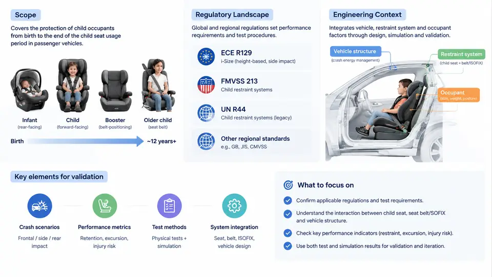
Child occupant protection (COP) sits at the intersection of crashworthiness engineering, restraint system design, biomechanics, and regulatory compliance. A child is not a scaled-down adult: the head represents a far larger fraction of total body mass, the neck is disproportionately weak, the pelvis is not fully ossified, and the rib cage deforms differently under belt loading. These anatomical realities mean that restraint systems validated for a 50th-percentile adult male Hybrid III dummy cannot simply be shrunk for a six-year-old. This course builds the engineering competence to design, test, and validate occupant protection systems specifically for children, from rear-facing infant seats through belt-positioning boosters.
Why a Dedicated Discipline Exists
Motor vehicle crashes remain a leading cause of unintentional injury death for children above one year of age in most motorized countries. The countermeasures that reduced adult fatality rates — airbags, three-point belts, energy-absorbing steering columns — were optimized around adult anthropometry and, in some early configurations, actually increased injury risk for children. The rear-facing infant seat, the top tether, and the booster cushion each emerged because field data and crash testing revealed distinct injury mechanisms that adult-oriented systems did not address.
Three injury mechanisms dominate the pediatric crash signature:
- Head and brain injury from contact with vehicle interior surfaces or from inertial loading of the disproportionately heavy head.
- Cervical spine injury from tension and bending moments that a child's ligamentous and bony neck cannot tolerate.
- Abdominal and spinal injury from "seat-belt syndrome" — the lap belt riding up over the iliac crests and loading soft tissue instead of the pelvis.
Each mechanism maps to a specific design countermeasure: rear-facing orientation distributes crash loads across the shell and backrest; top tethers limit forward head excursion; belt-positioning boosters route the lap belt onto the pelvic structure. Understanding this mapping is the foundation of the entire course.
The Regulatory Landscape
COP engineering operates under a layered regulatory and consumer-testing regime. The table below summarizes the principal frameworks a practicing engineer must navigate.
| Framework | Region | Scope | Key Characteristic |
|---|---|---|---|
| FMVSS 213 | United States | Child restraint systems for use in motor vehicles | Performance-based; sled test at 48 km/h; specifies injury criteria (HIC, chest deflection, head excursion) |
| FMVSS 213a / 213b | United States | Side-impact and updated frontal requirements | Adds oblique and side sled tests; introduces Q-series dummy requirements |
| ECE R44 | Europe / UN | Child restraint systems (legacy) | Weight-based classification; frontal and rear impact; phased out in favor of R129 |
| UN R129 (i-Size) | Europe / UN | Enhanced child restraint systems | Height-based classification; mandatory side-impact test; ISOFIX anchorage; Q-series dummies |
| GB 27887 | China | Child restraint systems | Harmonized with ECE R44; mandatory certification |
| Consumer tests (Euro NCAP, NHTSA NCAP) | Europe / US | Vehicle and CRS rating programs | Go beyond regulation; drive market differentiation |
Two structural shifts define the current landscape. First, the migration from weight-based (R44) to height-based (R129) classification reflects the recognition that seated height, not mass, determines whether a restraint fits correctly. Second, the adoption of the Q-series crash test dummies — Q0, Q1, Q1.5, Q3, Q6, Q10 — provides biofidelic instrumentation across the pediatric size range, replacing the older P-series and Hybrid III child dummies in new test protocols.
Engineering Context: From Regulation to Design
Regulatory compliance is the floor, not the ceiling. The engineering workflow for a child restraint system typically proceeds through concept definition, CAE-supported design iteration, prototype sled testing, and final certification. Each stage has its own validation logic.
Consider a representative frontal sled test for an R129-compliant Group 0+ rear-facing seat. The input is a sled pulse approximating a 50 km/h frontal impact — a deceleration-time history with peak around 28–30 g and a duration of roughly 100 ms. The seat is mounted on a test bench via ISOFIX lower anchors and a support leg. A Q1 dummy is positioned per the R129 installation procedure. Instrumentation includes head accelerometers (triaxial), upper neck load cell, and chest deflection sensor.
The key measured outputs and their typical acceptance thresholds are:
- Head Injury Criterion (HIC15): must not exceed 800 for the Q1 dummy under R129.
- Head excursion: forward displacement of the head must remain within the prescribed envelope — no contact with the test bench interior beyond the defined boundary.
- Upper neck tension and bending moment: evaluated against Q1-specific IARVs derived from pediatric tolerance data.
- Chest deflection: limited to prevent internal organ injury.
If a prototype fails, the failure mode itself is diagnostic. Excessive head excursion in a rear-facing seat often points to excessive shell rotation — the seat pitches forward about the ISOFIX anchors, allowing the dummy's head to move further than the envelope permits. The corrective action is typically to increase structural stiffness in the shell or to optimize the load path through the support leg. Excessive neck tension, by contrast, may indicate that the head is being restrained too abruptly, transferring load to the neck; here the solution may be to tune the energy absorption of the shell or the harness webbing.
Course Structure and Learning Path
This course is organized into six thematic blocks. The first block (Chapters 1–5) establishes the regulatory, biomechanical, and anthropometric foundations. The second block (Chapters 6–11) covers restraint system types and their design principles — rear-facing infant seats, forward-facing harnessed seats, boosters, and integrated vehicle restraints. The third block (Chapters 12–17) addresses crash test methodology, dummy instrumentation, and data analysis. The fourth block (Chapters 18–22) examines vehicle-level integration: ISOFIX/LATCH anchorage, top tether routing, airbag interaction, and occupant packaging. The fifth block (Chapters 23–27) covers validation, certification, and quality assurance. The final block (Chapters 28–30) explores emerging topics: side-impact protection, automated vehicle implications, and global harmonization efforts.
By the end of this course, you should be able to read a regulatory test protocol and identify the critical parameters, interpret dummy injury data against the correct IARVs, diagnose common failure modes from test results, and make informed design trade-offs between structural stiffness, energy absorption, and occupant kinematics.
The diagram above traces the complete validation chain: regulatory requirements define the test conditions and injury thresholds; pediatric biomechanics establishes the tolerance basis for those thresholds; restraint design translates the requirements into structural and kinematic countermeasures; sled testing with Q-series dummies produces the measured outputs; and the pass/fail decision against IARVs either leads to certification or triggers a diagnostic redesign loop. This chain is the backbone of every chapter that follows.
Key Takeaways
- Child occupant protection is a distinct engineering discipline because pediatric anatomy and injury tolerance differ fundamentally from adults.
- The regulatory landscape is layered: FMVSS 213/213a in the US, UN R129 (i-Size) in Europe and increasingly globally, with consumer test programs pushing beyond minimum compliance.
- The Q-series dummy family and height-based classification represent the current state of the art in biofidelic testing and fitment logic.
- Validation is a closed-loop process: test, measure against IARVs, diagnose failure modes, and iterate the design.
- Understanding the "why" behind each requirement — the injury mechanism it addresses — is what separates a compliance engineer from a safety engineer.