4. Occupant positioning and dummy models
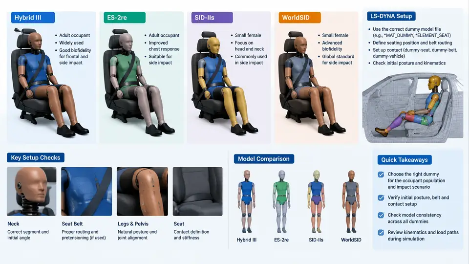
Side impact occupant restraint simulation is only as credible as the seated occupant it represents. In LS-DYNA, the dummy model is not a passive passenger — it is an assembly of rigid bodies, joints, deformable segments, and contact surfaces whose initial position, orientation, and belt routing determine the entire injury-response chain. This chapter covers the four dummy families most commonly used in side impact work, their positioning conventions, and the practical steps required to seat them correctly in a *KEYWORD deck.
Choosing the Right Dummy for the Impact Configuration
The four models are not interchangeable. Each was developed for a specific regulatory or consumer-test environment, and their biofidelity, geometry, and instrumentation differ accordingly.
| Model | Primary Use | Key Characteristics |
|---|---|---|
| Hybrid III 50th | FMVSS 208 frontal; baseline reference | Rigid spine, no side-specific instrumentation; used for comparison only |
| ES-2re | FMVSS 214 side impact (driver/passenger) | Rigid pelvis, deformable ribcage, 3-rib chest deflection; 50th percentile male |
| SID-IIs | FMVSS 214 side impact (small occupant) | 5th percentile female; smaller pelvis and thorax; used for out-of-position and small-occupant assessment |
| WorldSID 50th | Euro NCAP, UN R95, global harmonized side impact | Biofidelic ribcage with 4-rib deflection, improved pelvis and abdomen; anthropometry closer to modern population |
In a typical LS-DYNA side impact study, the ES-2re or WorldSID is placed on the struck side, while a Hybrid III may be placed on the non-struck side for comparison. The choice must be documented because injury criteria (e.g., RibDeflection, VC, TTI, ASIS force) are model-specific and cannot be transferred between dummy types.
Positioning Conventions and Coordinate Systems
All dummy models in LS-DYNA are delivered in a local coordinate system that must be aligned with the vehicle interior. The standard convention for side impact is:
- X-axis: longitudinal, positive forward (vehicle direction of travel).
- Y-axis: lateral, positive toward the struck side (left or right depending on impact side).
- Z-axis: vertical, positive upward.
The dummy's H-point (hip point) is the reference origin. In the LS-DYNA keyword deck, the dummy is typically defined as a separate include file with its own *PART, *CONSTRAINED_JOINT, and *MAT entries. Positioning is achieved by applying a *INITIAL_VELOCITY or, more commonly, by translating and rotating the entire dummy assembly using *INITIAL_VELOCITY_GENERATION with a prescribed motion, or by directly editing the node coordinates in the include file.
Seating the Dummy: From H-Point to Belt Routing
The seating process follows a defined sequence. First, the seat model is positioned and its foam or rigid surfaces are defined. The dummy is then placed so that its H-point coincides with the seat reference point (SgRP) within ±5 mm in X and Z, and ±2 mm in Y. This is verified by outputting the dummy's H-point node and comparing it to the target.
Next, the pelvis is oriented. For ES-2re and WorldSID, the pelvis angle is typically set to 20–25° from vertical, matching the seat pan angle. The lumbar spine is then adjusted to achieve the target torso angle (usually 25° for WorldSID, 22° for ES-2re). These angles are not arbitrary — they are specified in the dummy's user manual and must be reproduced to maintain biofidelity.
Belt routing is the most error-prone step. The belt must pass over the shoulder, across the chest, and through the pelvis without intersecting the dummy's rigid components. In LS-DYNA, this is handled by *ELEMENT_SEATBELT and *ELEMENT_SEATBELT_SLIPRING definitions. The belt path is defined by a series of nodes; if a node lies inside the dummy's geometry, the belt will penetrate and produce non-physical forces.
*ELEMENT_SEATBELT
$#  sid1      sid2      sid3      sid4      sid5      sid6      sid7      sid8
         1         2         3         4         5         6         7         8
$#  n1        n2        n3        n4        n5        n6        n7        n8
    100001    100002    100003    100004    100005    100006    100007    100008
$#  lcid      slip      ...
         0         0
After belt definition, a pre-simulation is run with the dummy held in place by a *BOUNDARY_PRESCRIBED_MOTION or a short settling phase. The purpose is to allow the belt to tension and the dummy to settle into the seat before the impact pulse is applied. Typical settling time is 20–50 ms with gravity loading.
Verification and Common Failure Modes
Before running the full side impact simulation, verify the following:
- H-point location: within tolerance of SgRP.
- Belt penetration: no belt node inside dummy geometry; check with
*DATABASE_ASCIIoutput of belt forces. - Initial penetration: run a
*CONTACTcheck; zero initial penetration is required. - Joint angles: match the dummy manual; output joint coordinates and compare.
- Mass and inertia: verify total dummy mass against the model specification (e.g., ES-2re ≈ 78 kg).
Common failure symptoms include: (1) belt forces spiking at t=0, indicating initial penetration; (2) dummy sliding out of position during settling, indicating insufficient friction or incorrect seat angle; (3) rib deflection output showing zero, indicating the deflection sensor is not activated or the rib part is not included in the contact definition.
Model-Specific Setup Notes
Hybrid III: In side impact, the Hybrid III is typically used only as a reference. Its rigid spine and lack of side instrumentation make it unsuitable for side injury assessment. If used, ensure the neck and lumbar joints are free to rotate; otherwise, the head may not respond correctly to lateral loading.
ES-2re: The ES-2re has a deformable ribcage with three ribs. The rib deflection is measured by *ELEMENT_DISCRETE or *SECTION_SHELL output. The pelvis is rigid and includes an ASIS force transducer. Ensure the ASIS load cell is oriented correctly — it measures force in the Y-direction.
SID-IIs: The SID-IIs is smaller and lighter (≈ 45 kg). Its ribcage is also deformable, but the deflection range is smaller. The pelvis is rigid. Because of its size, belt routing is more critical; the belt may slip off the shoulder if the torso angle is too far reclined.
WorldSID: The WorldSID has a four-rib deformable thorax and an abdomen with a separate deflection measurement. It is the most biofidelic of the four but also the most complex. The arm position must be set according to the test protocol (e.g., 45° forward for Euro NCAP). The pelvis includes a pubic symphysis load cell. Ensure all instrumentation channels are activated in *DATABASE_ASCII.
The diagram above summarizes the positioning workflow and the key parameters that must be verified before running a side impact simulation. The dummy model selection (bottom left) feeds into the placement and verification steps, and the coordinate system convention (bottom right) applies to all translations and rotations.
Summary
Correct dummy setup in LS-DYNA side impact simulation requires more than importing a model. It demands alignment with the vehicle coordinate system, precise H-point placement, adherence to model-specific joint angles, and careful belt routing. The ES-2re and WorldSID are the primary tools for side impact injury assessment, while the SID-IIs addresses small occupants and the Hybrid III serves as a reference. Verification of initial penetration, belt forces, and mass properties is mandatory before any impact pulse is applied. When these steps are followed, the dummy becomes a reliable instrument for predicting occupant response rather than a source of numerical noise.