1. Side impact crashworthiness fundamentals
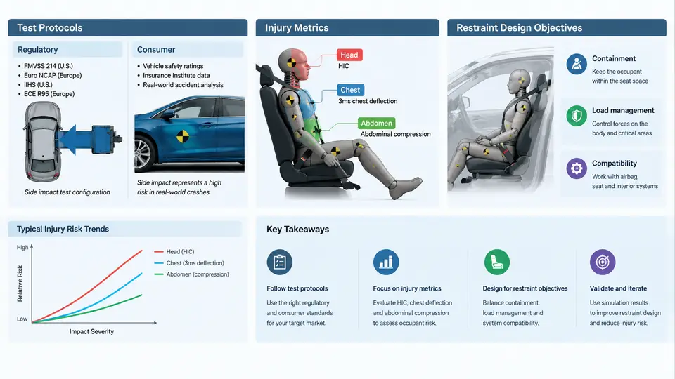
Side impact is one of the most demanding load cases in occupant safety engineering. Unlike frontal crashes, where a long crumple zone and the restraint system share the energy absorption task over 80–120 ms, a lateral strike offers only 200–400 mm of deformable structure between the striking vehicle and the occupant. The occupant and the intruding door panel are separated by a gap that is often smaller than the thickness of a human torso. This geometric reality drives every design decision in a side impact restraint program: there is little time, little space, and almost no margin for error.
This chapter establishes the regulatory and consumer-test landscape, the injury metrics used to judge occupant protection, and the restraint design objectives that follow from them. These three elements form the foundation on which every subsequent LS-DYNA model, material card, and contact definition in this course is built.
Regulatory and Consumer Test Protocols
Two families of side impact tests dominate global practice: regulatory tests that establish minimum legal compliance, and consumer tests that drive star ratings and market perception. The most widely referenced regulatory procedures are FMVSS 214 (United States), ECE R95 (Europe), and GB 20071 (China). Consumer programs include Euro NCAP, US NCAP, C-NCAP, and IIHS. Each defines a specific moving deformable barrier (MDB), impact angle, impact speed, and occupant seating position.
FMVSS 214 specifies a crabbed MDB weighing approximately 1,368 kg impacting the stationary test vehicle at 54 km/h with a 27° crab angle. The barrier face is designed to represent a typical passenger car front end. ECE R95 uses a heavier 950 kg barrier at 50 km/h with a perpendicular impact. Euro NCAP's side barrier test uses a 1,300 kg MDB at 60 km/h, while its more severe side pole test drives the vehicle laterally into a rigid 254 mm diameter pole at 32 km/h. The pole test is particularly relevant to restraint design because it produces concentrated intrusion directly at the occupant's chest and abdomen.
The choice of barrier, speed, and angle determines the intrusion pulse that the restraint system must manage. A 60 km/h MDB impact generates door intrusion velocities of 8–12 m/s at the occupant's hip and chest, whereas the pole test produces localized intrusion of 300–500 mm with a much sharper velocity profile. These differences mean that a restraint system optimized for one test may perform poorly in another, which is why modern side impact programs are validated against multiple protocols simultaneously.
Injury Metrics and Their Physical Meaning
Injury metrics translate measured physical quantities—acceleration, force, deflection—into a normalized number that correlates with real-world injury risk. In side impact, the most important metrics are:
- HIC (Head Injury Criterion) — derived from resultant head acceleration over a 15 ms window. In side impact, head contact with the intruding B-pillar or window glass is a primary concern.
- Rib Deflection Criterion (RDC) — maximum rib deflection measured by chestbands or IR-TRACC sensors. Euro NCAP limits chest deflection to 42 mm for the 50th percentile male.
- VC (Viscous Criterion) — the product of chest compression velocity and instantaneous compression, capturing soft-tissue injury risk that pure deflection misses.
- TTI (Thoracic Trauma Index) — used in US NCAP, combining chest and pelvis acceleration.
- Pelvis force and pubic symphysis force — measured via load cells in the WorldSID or ES-2re dummy.
The ES-2re and WorldSID 50th percentile male dummies are the primary tools for these measurements. The WorldSID offers improved biofidelity, particularly in the abdomen and pelvis, and is now required in Euro NCAP and C-NCAP side impact tests. Understanding which dummy and which sensor channels are active in a given protocol is essential before interpreting any simulation output.
Restraint Design Objectives
Side impact restraint systems must accomplish three objectives within a 30–50 ms window: (1) couple the occupant to the vehicle early enough to benefit from the vehicle's own deceleration, (2) distribute restraint forces over the strongest load paths—pelvis, chest, and shoulder—while avoiding concentrated loading on the abdomen, and (3) manage head kinematics to prevent contact with intruding structures or the far-side interior.
The primary restraint elements are the side airbag (thorax and/or pelvis), the side curtain airbag, and the seat belt with pretensioner and load limiter. The side airbag must deploy in 10–20 ms and reach full pressure before the occupant's chest moves more than 50 mm laterally. The curtain airbag must remain inflated for 3–5 seconds to protect against ejection and far-side head contact in rollover or secondary impacts.
Design objectives are typically expressed as target values at specific time points. For example, a thorax side airbag might be designed to achieve a chest deflection of less than 35 mm at 40 ms after impact, with a bag pressure of 150–250 kPa and a vent size that allows controlled deflation. These targets are not arbitrary; they are derived from the injury metric thresholds and the intrusion pulse of the target vehicle platform.
From Protocol to Simulation: What This Means for LS-DYNA
Every LS-DYNA side impact model must reproduce the boundary conditions of the target protocol. That means the correct MDB geometry and mass, the correct impact velocity and angle, the correct dummy model (ES-2re or WorldSID), and the correct sensor locations. The intrusion pulse measured on the door inner panel becomes the primary input to the restraint design; if the simulation does not match the physical intrusion profile, the airbag timing and venting will be wrong regardless of how refined the occupant model is.
A practical workflow begins with a vehicle-level model that captures the door, B-pillar, rocker, and seat structure. The MDB is positioned according to the protocol, and a rigid-wall or full-vehicle simulation is run to extract the intrusion velocity at the occupant's hip and chest. This velocity profile is then applied to a sled or full-vehicle occupant model. The restraint system—side airbag, curtain airbag, belt—is tuned until the injury metrics fall below the target thresholds with adequate margin.
Design Objectives in Practice
Restraint design objectives are typically stated as a set of target values at specific time points, derived from the injury metric thresholds and the intrusion pulse. A representative objective set for a Euro NCAP side barrier test might be:
| Metric | Target | Measurement Point | Time Window |
|---|---|---|---|
| Chest deflection (RDC) | ≤ 35 mm | WorldSID rib IR-TRACC | Peak, 20–60 ms |
| VC | ≤ 0.8 m/s | WorldSID chest | Peak, 20–60 ms |
| Pelvis force | ≤ 3.5 kN | WorldSID pelvis load cell | Peak, 15–50 ms |
| Abdomen force | ≤ 2.0 kN | WorldSID abdomen | Peak, 15–50 ms |
| Head HIC | ≤ 500 | WorldSID head CG | 0–80 ms |
These targets are not achieved by a single component. The side airbag must be sized to cover the chest and pelvis, with a vent that controls pressure decay. The curtain airbag must deploy downward to cover the window opening and provide a cushion between the head and the B-pillar. The seat belt pretensioner must fire within 10–15 ms to remove slack and couple the occupant to the seat early. The load limiter must allow controlled belt payout to reduce chest loading while maintaining pelvis engagement.
The interaction between these components is where simulation becomes indispensable. A stiffer airbag may reduce chest deflection but increase VC by transferring load too quickly. A larger vent may reduce VC but allow the chest to bottom out against the door. LS-DYNA allows these trade-offs to be explored systematically through parametric studies, design of experiments, and optimization loops.
Summary
Side impact crashworthiness is defined by the protocols that set the boundary conditions, the injury metrics that quantify occupant risk, and the restraint design objectives that translate those metrics into engineering targets. The MDB impact, the pole test, and the various dummy models each impose different demands on the restraint system. Understanding these demands—and the physical mechanisms behind them—is the prerequisite for building a valid LS-DYNA model. In the chapters that follow, each of these elements will be developed into a concrete modeling and simulation workflow.