1. Side airbag systems in vehicle safety
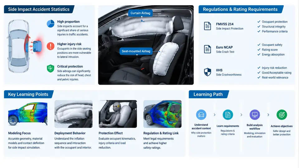
Side airbags address a fundamentally different collision environment than frontal airbags. In a frontal crash, the occupant moves forward into a relatively large crush zone, and the restraint system has tens of milliseconds of ride-down distance to manage. In a side impact, the striking vehicle or pole can intrude into the occupant compartment within 10–20 ms, and the distance between the occupant's thorax and the door trim is often only 100–250 mm. The side airbag must therefore inflate faster, occupy a smaller volume, and be packaged inside the seat, door, or roof rail. Understanding the types of side airbags, how they deploy, and what injury mechanisms they are designed to mitigate is the foundation for every subsequent LS-DYNA modeling decision.
Types of Side Airbag Systems
Side airbag systems are classified by the body region they protect and by their mounting location. The four common configurations are:
- Thorax side airbag (torso bag): mounted in the outboard side of the seat backrest. It deploys forward and slightly upward to cover the occupant's chest and abdomen, cushioning the gap between the torso and the door trim.
- Combined thorax–pelvis airbag: a single larger bag with internal tethers or chambers that simultaneously cover the rib cage and the pelvis, reducing both chest deflection and pelvic fracture risk.
- Head side airbag (curtain or tubular): mounted along the roof rail or within the seat. It deploys downward to cover the side window and B-pillar area, preventing head contact with the glass, pillar, or intruding structure.
- Combined head–thorax airbag: a single module that inflates both a head curtain section and a torso section, commonly used when packaging space or cost favors one inflator.
In addition, far-side airbags (mounted on the inboard side of the seat) have become more common because they protect the occupant from striking the center console or the opposite-side occupant during a far-side impact. Each type has a distinct deployment trajectory, fill volume, and pressure history, and these differences directly determine how the LS-DYNA model must be built.
Deployment Mechanisms
Nearly all production side airbags use a pyrotechnic inflator, either a hybrid inflator (compressed gas plus a small pyrotechnic charge) or a solid-propellant inflator. The deployment sequence is triggered by a side-impact sensor, typically an accelerometer or pressure sensor mounted in the B-pillar, door, or sill. The sensing and deployment timeline is extremely short:
| Event | Typical Time (ms) | Notes |
|---|---|---|
| Impact initiation | 0 | Striking barrier contacts the door or sill |
| Sensor detection | 2–5 | Acceleration or pressure threshold exceeded |
| Deployment decision | 5–8 | Algorithm confirms side impact, fires squib |
| Inflator gas generation | 8–12 | Propellant burns, gas fills the bag |
| Bag fully inflated | 15–25 | Bag contacts occupant and door trim |
| Occupant loading | 20–40 | Bag compresses, vents gas, absorbs energy |
The inflator output is characterized by a mass flow rate curve and a gas temperature. In LS-DYNA, this is typically represented with the *AIRBAG_SIMPLE_PRESSURE_VOLUME or *AIRBAG_WANG_NEFSKE keyword, where the user supplies a tank pressure curve or a mass flow rate versus time. The bag fabric is modeled with membrane elements and a fabric material such as *MAT_FABRIC, with permeability and leakage defined through *AIRBAG_REFERENCE_GEOMETRY and vent hole definitions.
Key modeling implication: The deployment timing and inflator mass flow rate are not arbitrary inputs. They must match the physical inflator's tank test data. A common error is to use a generic pressure curve that inflates the bag too slowly, which causes the bag to miss the occupant and under-predict chest deflection.
Occupant Protection Objectives
Side airbags are designed to reduce specific injury measures. For the thorax, the primary objective is to limit rib deflection and the Viscous Criterion (VC), which combines chest compression and compression velocity. For the head, the objective is to prevent contact with the B-pillar, window glass, or intruding door structure, keeping the Head Injury Criterion (HIC) below regulatory and consumer-test thresholds. For the pelvis, the goal is to distribute load across the iliac wing and avoid concentrated force that can cause fracture.
The protection mechanism is not simply "cushioning." The bag must:
- Deploy into the gap between the occupant and the door before the occupant moves laterally.
- Provide a compliant but load-bearing surface that distributes force over a larger area.
- Vent gas in a controlled manner so that the occupant decelerates rather than rebounds.
- Maintain coverage of the head and thorax throughout the impact duration, typically 80–120 ms.
These objectives translate directly into LS-DYNA model requirements: the bag geometry must match the packaged and deployed shape, the fabric must have realistic stiffness and permeability, the venting must be calibrated, and the occupant model must be positioned to represent the actual seating posture. The following SVG summarizes the relationship between airbag type, deployment path, and the protected body region.
From Protection Objective to Simulation Input
The practical consequence of this classification is that each airbag type imposes different requirements on the LS-DYNA model. A thorax bag model must capture the interaction between the bag and the seat frame, the door trim, and the occupant's rib cage. A head curtain model must capture the bag's interaction with the window glass and the B-pillar, and it must remain inflated long enough to provide coverage during a rollover or a secondary impact. A pelvis bag model must account for the seat cushion and the lower door structure.
When setting up a side airbag simulation, the following inputs are typically required and should be verified against physical test data:
- Inflator mass flow rate: derived from tank tests, entered as a curve in
*AIRBAG_SIMPLE_PRESSURE_VOLUMEor*AIRBAG_WANG_NEFSKE. - Bag geometry: folded and unfolded configurations, defined with
*AIRBAG_REFERENCE_GEOMETRYand membrane elements. - Fabric properties: Young's modulus, Poisson's ratio, and permeability, defined in
*MAT_FABRIC. - Vent hole area: controls the pressure decay and occupant deceleration.
- Contact definitions: bag-to-occupant, bag-to-door, and bag-to-seat contacts, using
*CONTACT_AUTOMATIC_SURFACE_TO_SURFACEor*CONTACT_AIRBAG_SINGLE_SURFACE.
Practical check: Before running a full occupant simulation, run a standalone bag deployment with the inflator curve and verify that the bag reaches the target volume and pressure at the expected time. If the bag inflates too slowly, the occupant will not be restrained; if it inflates too quickly, the bag may cause injury itself. This standalone check is faster and isolates inflator and fabric issues from occupant positioning issues.
Summary
Side airbags are not a single product but a family of systems differentiated by protected region, mounting location, and deployment trajectory. Thorax bags, head curtains, pelvis bags, and combined modules each have distinct inflator characteristics, bag geometries, and venting strategies. Their common objective is to manage the extremely short time and distance available in a side impact, limiting chest deflection, head injury, and pelvic fracture. In LS-DYNA, these physical differences must be represented through accurate inflator curves, fabric properties, and contact definitions. The next chapters will build on this foundation by examining how to construct and validate each of these models in detail.