4. Seat and interior environment modeling
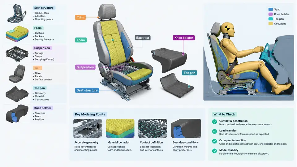
In a frontal occupant restraint simulation, the seat and surrounding interior surfaces are not passive scenery. They define the occupant's initial posture, control how the body loads the restraint system, and absorb or redirect energy during the crash pulse. A model that treats the seat as a rigid block and the toe pan as an immovable wall will produce belt forces and injury metrics that look plausible but are physically wrong. This chapter covers how to represent the seat structure, foam, suspension, trim, toe pan, and knee bolster so that occupant interaction is captured with the fidelity the restraint design actually requires.
Role of the Interior in the Restraint Load Path
During a frontal impact the occupant moves forward relative to the vehicle. The restraint system — belt, pretensioner, load limiter, airbag — controls the upper torso and head, but the lower body is controlled by the seat cushion, the knee bolster, and the toe pan. If the pelvis submarines under the lap belt, the belt loads the abdomen instead of the iliac crest. If the knee bolster is too soft, the knees travel too far and the pelvis rotates forward. If the toe pan is rigid, the feet lock and the tibia loads spike. Each of these outcomes depends on how the interior is modeled.
The practical consequence is that interior models must be calibrated against component tests, not guessed. A seat cushion that is 30% too stiff will under-predict pelvis excursion and over-predict lap belt force. The sections below describe the representation strategy for each component and the parameters that matter most.
Seat Structure
The seat frame — cushion pan, back frame, recliner, and tracks — carries the occupant's inertial load into the floor. In most frontal simulations the frame is represented with shell elements and a rigid or elastic-plastic material. The key decision is whether the seat back is allowed to rotate. A locked recliner can be modeled as rigid; a recliner that yields under load must be represented with a plastic hinge or a connector with a defined moment-rotation curve.
For a typical driver seat, a reasonable starting representation is:
- Cushion pan and back frame:
*MAT_ELASTIC_PLASTICsteel, shell elements, 5–8 mm mesh. - Recliner:
*CONSTRAINED_JOINT_REVOLUTEwith a moment-rotation curve from the supplier, or a rigid joint if the design is locked. - Tracks: rigid or elastic, with the floor attachment represented by
*CONSTRAINED_SPOT_WELDor tied contacts.
The seat back angle at the start of the simulation must match the test setup. A 3° error in back angle changes head-to-belt geometry and shifts head excursion by 20–40 mm in a 50 km/h frontal pulse.
Foam and Suspension
Seat foam is the primary interface between the occupant and the seat structure. It is highly nonlinear, rate-sensitive, and compresses 60–80% under occupant loading. The standard representation is a solid element mesh with *MAT_LOW_DENSITY_FOAM or *MAT_SOFT_TISSUE, driven by a uniaxial compression stress-strain curve.
A typical polyurethane cushion foam curve for a frontal application:
*MAT_LOW_DENSITY_FOAM
$   MID        RO        E        TC        HU
     1    5.0E-11   2.0E+00   1.0E-01   0.0E+00
$   LCID
     100
$ Strain    Stress (MPa)
   0.00      0.000
   0.10      0.015
   0.30      0.045
   0.50      0.090
   0.70      0.180
   0.80      0.320
   0.90      0.600
The suspension — the spring grid or elastic membrane under the foam — is often modeled as a membrane with *MAT_FABRIC or as a set of nonlinear springs. Its role is to keep the foam from bottoming out against the pan. If the suspension is omitted, the foam compresses too far and the pelvis sits lower than in the test.
Trim and Toe Pan
Trim covers — seat back panel, side bolsters, and headrest — are usually represented as shell elements with *MAT_FABRIC or *MAT_ELASTIC. Their main function is to provide contact surfaces for the occupant and the airbag. A missing seat back panel allows the airbag to expand into the seat instead of toward the occupant, which changes head kinematics significantly.
The toe pan is the floor surface ahead of the pedals. In a frontal crash the feet slide forward and the toe pan limits their travel. It is typically modeled as rigid or elastic shell, tied to the floor structure. The critical parameter is the toe pan angle: a 10° change in toe pan angle alters tibia loading by 15–25% because it changes the direction of the foot reaction force.
Knee Bolster
The knee bolster is the most influential interior component for lower-extremity injury. It is a energy-absorbing panel mounted below the instrument panel. Its representation depends on the design:
| Design | Modeling Approach | Key Parameter |
|---|---|---|
| Rigid bolster | Rigid shell, fixed | Position and angle |
| Plastic deformable | Shell with *MAT_PLASTIC_KINEMATIC | Yield stress, thickness |
| Foam-backed | Solid foam + shell backing | Foam curve, backing stiffness |
| Active/retractable | Spring or connector with deployment | Deployment timing, stroke |
For a deformable bolster, the force-deflection curve from a knee impact test is the calibration target. A typical target for a 50th percentile male is 4–6 kN at 50 mm deflection. If the model predicts 8 kN, the bolster is too stiff and the tibia index will be over-predicted.
Interaction and Contact Definitions
The interior components interact with the occupant through contact. The essential contacts are:
- Occupant pelvis to seat cushion foam:
*CONTACT_AUTOMATIC_SURFACE_TO_SURFACE, friction 0.3–0.5. - Occupant back to seat back foam: same contact, friction 0.3.
- Occupant knees to knee bolster:
*CONTACT_AUTOMATIC_SURFACE_TO_SURFACE, friction 0.2–0.3. - Occupant feet to toe pan:
*CONTACT_AUTOMATIC_SURFACE_TO_SURFACE, friction 0.5–0.7. - Airbag to seat back and bolster:
*CONTACT_AIRBAG_SINGLE_SURFACE.
Friction values matter. A lap belt friction of 0.1 versus 0.5 changes pelvis excursion by 15–20 mm. Use values from material tests, not defaults.
Calibration Workflow
Build the interior model in stages. First, run a seat cushion indentation simulation and match the force-deflection curve. Second, run a knee bolster impact simulation and match the force-deflection curve. Third, run a full occupant model with the calibrated interior and compare pelvis excursion, knee travel, and tibia force against sled test data. If the pelvis excursion is too small, soften the cushion or reduce friction. If the tibia force is too high, soften the bolster or increase the toe pan angle.
Summary
Seat structure, foam, suspension, trim, toe pan, and knee bolster each contribute to the occupant load path. The seat frame and recliner define posture and load transfer. The foam and suspension define pelvis position and cushioning. The trim provides contact surfaces. The toe pan and knee bolster control lower-extremity kinematics and injury. Model each with the appropriate element type and material, calibrate against component tests, and verify with a full occupant run. The next chapter applies these interior models to the complete frontal restraint simulation.