1. Frontal occupant restraint simulation sc
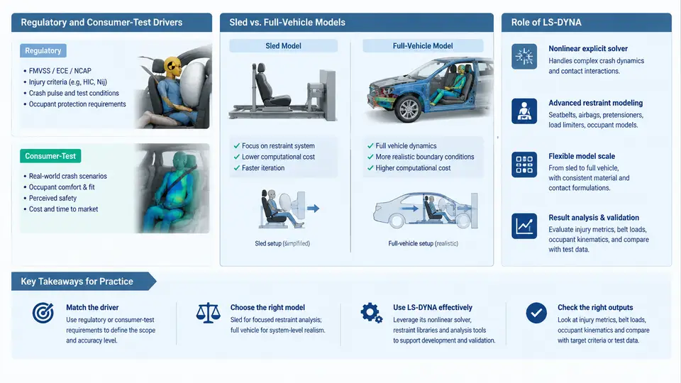
Frontal occupant restraint simulation is the virtual counterpart of the physical crash test. Its purpose is to predict how a restrained occupant moves, loads the belt and airbag, and interacts with the vehicle interior during a frontal impact, and to do so early enough that restraint design decisions can still be changed cheaply. In an LS-DYNA-based workflow, this means building a model in which the vehicle structure, the restraint hardware, and the occupant are all represented, then solving the coupled kinematics with explicit time integration. Before any of that is useful, however, the engineer must understand why the simulation exists, what it must reproduce, and which model fidelity is appropriate at each stage of a program.
Regulatory and Consumer-Test Drivers
Restraint performance is not judged in the abstract; it is judged against defined test procedures. Two families of requirements dominate frontal restraint engineering.
Regulatory tests establish the legal minimum. In the United States, FMVSS 208 defines frontal barrier and offset deformable barrier tests with unbelted and belted occupants, and specifies injury criteria such as HIC15, chest deflection, and femur axial force. In Europe and many other markets, UN Regulation No. 94 and No. 137 govern frontal impact protection and belt anchorage. These tests are pass/fail: the vehicle must not exceed the criteria, and the restraint must deploy correctly.
Consumer tests go beyond the legal floor and produce a star rating or score. Euro NCAP's frontal offset and mobile progressive deformable barrier tests, and the equivalent IIHS moderate overlap and small overlap evaluations, use instrumented ATDs (Anthropomorphic Test Devices) and increasingly human body models to rate occupant protection. Because a low star rating directly affects market perception, consumer protocols often drive restraint calibration targets more aggressively than regulation does.
The practical consequence for simulation is that the load cases, impact speeds, barrier geometry, and injury criteria are all prescribed. The model must reproduce those boundary conditions faithfully, and the output must be expressed in the same metrics the test house will measure. A simulation that predicts "good occupant kinematics" but cannot output HIC15 or chest deflection in the correct channel is not useful for certification support.
Sled versus Full-Vehicle Models
Frontal restraint simulation is normally executed in two distinct model classes, and understanding when to use each is a core competency.
A sled model represents the occupant compartment, seats, belts, airbags, and ATDs, but replaces the vehicle body with a prescribed deceleration pulse applied to the sled structure. The pulse is derived from a full-vehicle crash test or a previous full-vehicle simulation. Because the body is rigid or simplified, the sled model is small, fast, and highly repeatable. It is the workhorse for restraint parameter studies: belt force limiter levels, pretensioner timing, airbag vent sizing, seat position, and occupant size variations can be swept in hours rather than days.
A full-vehicle model includes the complete body-in-white, closures, suspension, and the restraint system, and is solved against a barrier. It captures the coupling between structural deformation and restraint loading: the steering column and knee bolster intrusion, the seat track deformation, and the timing of the occupant relative to the vehicle deceleration all emerge from the model rather than being prescribed. Full-vehicle models are essential for validating the pulse used in the sled, for assessing structural intrusion effects, and for final confirmation before a physical test.
The relationship between the two is directional. The full-vehicle model generates the pulse and the intrusion boundary conditions; the sled model consumes them and is used for the bulk of the calibration. A well-run program iterates: sled calibration informs restraint design, the design is inserted into the full-vehicle model, and the resulting pulse is fed back to the sled.
The Role of LS-DYNA in Restraint System Development
LS-DYNA is the dominant explicit finite element solver for crashworthiness and occupant safety, and its restraint-specific capabilities are what make it central to this workflow.
Occupant and restraint modeling. LS-DYNA provides dedicated material and element formulations for restraint hardware. Seatbelts are modeled with seatbelt elements and slip rings, using *MAT_SEATBELT and *ELEMENT_SEATBELT_ACCELEROMETER for retractor and pretensioner behavior. Airbags use *AIRBAG keywords, including *AIRBAG_WANG_NEFSKE for uniform-pressure (control volume) modeling and *AIRBAG_PARTICLE for more detailed gas dynamics. ATDs are typically imported as validated rigid/flexible occupant models with joints and accelerometers already defined.
Coupling and contact. The occupant interacts with the belt, airbag, seat, and interior through contact definitions. Belt-to-occupant contact, airbag-to-occupant contact, and occupant-to-interior contact must all be defined with appropriate friction and penetration control. This is where most model quality problems appear: a belt that slips through the occupant, or an airbag that penetrates the chest, will produce non-physical injury values.
Injury criteria post-processing. LS-DYNA outputs the raw time histories; the criteria are computed in post-processing. HIC15 is calculated from the resultant head acceleration over the most severe 15 ms window. Chest deflection is taken from the ATD's chest potentiometer or IR-TRACC channel. Femur force is read from the load cell. These must be filtered per the protocol before the criterion is evaluated.
Positioning and pre-simulation. Before the impact simulation, the occupant must be seated and belted in a settled position. LS-DYNA's *INITIAL_FOAM_REFERENCE_GEOMETRY and seatbelt fitting routines, or a separate pre-simulation with gravity and belt tensioning, establish this state. Starting the impact run from an unstressed belt will produce a non-physical slack period.
What a First Working Model Looks Like
A practical starting point for a frontal sled model in LS-DYNA contains the following minimum set of components and settings. This is a teaching example, not a validated model.
*KEYWORD
*CONTROL_TERMINATION
$ endtim = 150 ms, typical frontal sled duration
         150.0
*CONTROL_TIMESTEP
$ dtinit = 0 (auto), tssfac = 0.9
         0.0      0.9
*DATABASE_BINARY_D3PLOT
$ plot interval 1.0 ms
         1.0
*DATABASE_HISTORY_NODE
$ head CG node, chest node, pelvis node
         1001     1002     1003
*MAT_SEATBELT
$ mid, rho, young, pr, lcid, ... (belt material)
         10   1.0e-9  2000.0   0.3
*ELEMENT_SEATBELT_SLIPRING
$ slip ring definitions at D-ring and buckle
*AIRBAG_WANG_NEFSKE
$ driver airbag, control volume, mass flow rate curve
*CONSTRAINED_INTERPOLATION
$ optional: occupant positioning constraint
*CONTACT_AUTOMATIC_SURFACE_TO_SURFACE
$ belt-to-occupant, airbag-to-occupant, occupant-to-interior
*INCLUDE
$ occupant ATD model, seat model, interior model
*END
After the run, the engineer checks three things first: (1) the occupant kinematics animation, to confirm the head does not bottom out the airbag or slide off the belt; (2) the belt force time history, to confirm the force limiter is engaging at the intended level; and (3) the injury criteria, to confirm HIC15, chest deflection, and femur force are within the target envelope. If the head acceleration shows a sharp spike, the likely cause is airbag bottom-out or a contact penetration; if chest deflection is excessive, the belt force limiter may be set too high or the pretensioner timing too late.
Scope Summary
Frontal occupant restraint simulation in LS-DYNA sits at the intersection of prescribed test protocols and engineering design freedom. The regulatory and consumer tests define the load cases and the pass criteria; the sled and full-vehicle models divide the labor between fast parameter exploration and coupled structural verification; and LS-DYNA supplies the explicit solver, restraint-specific material models, and contact algorithms that make the coupled occupant–restraint–structure problem tractable. The engineer's task is to keep the model fidelity matched to the decision being made, to keep the output channels aligned with the test protocol, and to recognize the characteristic failure signatures that separate a numerical artifact from a real restraint problem.