1. Curtain airbag rollover protection simul
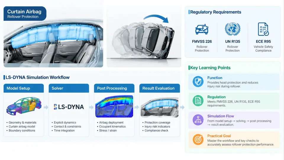
Curtain airbags (CABs) are inflatable side-impact restraints that deploy from the roof rail and cover the side glazing from the A-pillar to the C- or D-pillar. Their primary mission is to keep the occupant's head inside the vehicle and to cushion it against the side structure and glazing during a rollover or a far-side lateral impact. Because a rollover unfolds over hundreds of milliseconds and involves large rigid-body motion, roof crush, glazing fracture, and occupant excursion, the restraint must be evaluated with a simulation method that can handle nonlinear contact, airbag gas dynamics, and multi-body occupant kinematics simultaneously. LS-DYNA, with its explicit time integration, ALE/CPM gas modeling, and mature occupant dummies, is the de-facto industry tool for this class of problem.
1.1 What the simulation is actually asked to prove
A curtain airbag rollover simulation is not a single analysis but a chain of coupled models. The engineering objectives can be grouped into four verifiable claims:
- Deployment coverage: the inflated cushion must reach the required coverage envelope (typically the side glazing area between the A- and C-pillars) within a specified time after the trigger, without being trapped by trim or the headliner.
- Occupant containment: the head must not pass through the side glazing opening or beyond the cushion's outboard edge. This is measured by head excursion relative to the vehicle interior and by the head-to-cushion contact pattern.
- Injury metrics: the head injury criterion (HIC), the resultant head acceleration, and neck loads must stay below the limits defined by the applicable regulation or OEM internal target.
- Robustness: the restraint must still meet the above under off-nominal conditions — out-of-position (OOP) occupants, low-temperature gas generant performance, and worst-case roof crush.
These claims are what separates a decorative animation from an engineering deliverable. Every modeling decision — mesh size, gas model, contact definition, dummy positioning — should be traceable to one of them.
1.2 Regulatory and rating drivers
The regulatory landscape shapes both the load cases and the pass/fail thresholds. In the United States, FMVSS 226 (Ejection Mitigation) is the central driver: it uses a linear impactor fired at the side glazing to represent an occupant's head during a rollover, and requires that the head not be ejected through the side window opening. The test is quasi-static in nature but the restraint must be fully deployed and pressurized at the moment of impact. In Europe, UN Regulation No. 135 (pole side impact) and the broader rollover provisions of ECE R94/R95 influence side restraint design, while consumer programs such as Euro NCAP and US NCAP add rollover and far-side occupant rating tests. China's GB 26134 (roof crush) and the evolving GB side-impact standards add further constraints for vehicles sold in that market.
Two consequences follow for the CAE engineer. First, the load case is prescribed: impactor mass, velocity, impact point, and deployment timing are fixed by the regulation, so the simulation must reproduce them exactly. Second, the pass/fail criterion is geometric and measurable — head excursion or ejection — which means the simulation must predict geometry and timing accurately, not just produce plausible-looking motion.
1.3 Why LS-DYNA is the tool of record
LS-DYNA's explicit solver is built for transient, highly nonlinear events. For curtain airbags specifically, three capabilities matter:
- Gas modeling: the *AIRBAG_ keyword family supports uniform pressure (UP), control-volume (CV), and corpuscular particle method (CPM) gas models. CPM is preferred when the cushion has complex folding or when jetting and pressure gradients inside the bag affect deployment.
- Fabric and seam modeling: orthotropic fabric material models (*MAT_FABRIC) with leakage and permeability capture the cushion's structural response, while seam definitions control the inflated shape.
- Occupant and contact: the *CONSTRAINED_INTERPOLATION and *CONTACT_AUTOMATIC_SURFACE_TO_SURFACE cards couple the dummy to the cushion and the vehicle interior, and the dummy models (e.g., THOR, WorldSID, or the LSTC Hybrid III) are validated for the relevant load cases.
The practical workflow is a staged build: a standalone airbag deployment model to validate inflation timing and coverage, then a coupled occupant model that adds the dummy and the vehicle interior, and finally a full rollover or impactor model that adds the vehicle body and the regulatory boundary conditions. Skipping the standalone stage is a common source of wasted compute — if the cushion does not inflate correctly on its own, the coupled model will not either.
1.4 A concrete first load case
To make the objectives tangible, consider a representative FMVSS 226-style setup for a mid-size SUV. The linear impactor has a mass of 18 kg and is fired at 20 km/h (5.56 m/s) into the side glazing at a point 50 mm below the top of the window opening. The CAB is triggered 30 ms before impactor contact, and the gas generant mass flow follows the inflator's tank test curve. The occupant is a Hybrid III 50th percentile male positioned in the driver seat with the head 150 mm from the glazing.
In LS-DYNA, the load case is assembled as follows. The vehicle body is imported as a shell mesh with rigid roof rail and B-pillar sections. The CAB is modeled with *MAT_FABRIC (orthotropic, with permeability) and *AIRBAG_CPM; the inflator is defined by a *DEFINE_CURVE of mass flow rate versus time. The impactor is a rigid body with an initial velocity card. Contact between the impactor, the cushion, and the glazing is defined with *CONTACT_AUTOMATIC_SURFACE_TO_SURFACE, and the glazing is given a failure strain so it can fracture. The termination time is set to 150 ms, with output at 1 ms intervals for pressure, head acceleration, and contact force.
*MAT_FABRIC
$ mid, ro, ea, eb, ec, prba, prca, prcb
   100, 8.0e-7, 2.0e4, 2.0e4, 2.0e4, 0.3, 0.3, 0.3
$ ... permeability and leakage cards follow

*AIRBAG_CPM
$ sid, sidtyp, rbid, vsca, psca, ...
   200, 0, 0, 1.0, 1.0
$ mass flow rate curve
$ lcid: 300

*DEFINE_CURVE
   300, 0, 1.0, 1.0, 0.0, 0.0
$ time (ms), mass flow (kg/ms)
   0.0, 0.0
   5.0, 0.12
  15.0, 0.35
  25.0, 0.18
  35.0, 0.02
  45.0, 0.0

*CONTACT_AUTOMATIC_SURFACE_TO_SURFACE
$ ssid, msid, sstyp, mstyp, ...
   400, 500, 3, 3
$ fs, fd, dc, vc, ...
   0.3, 0.3, 0.0, 0.0
After the run, the engineer checks three things. First, the cushion pressure curve should peak between 20 and 40 ms and then decay as gas leaks through the fabric and seams; a pressure that never rises or rises too slowly indicates a mass-flow or CPM initialization error. Second, the head excursion plot should show the head moving outboard, contacting the cushion, and rebounding; if the head passes the cushion's outboard edge, the cushion is either under-inflated or the folding is trapping gas. Third, the impactor force should show a distinct plateau corresponding to cushion compression; a force spike without a plateau suggests the impactor is hitting the glazing directly, meaning the cushion did not deploy in time.
1.5 What success looks like
A successful Chapter 1-level simulation is not a single number but a consistent story: the cushion deploys within the target time, covers the glazing, the head contacts the cushion rather than the glazing or the pillar, and the injury metrics stay below the thresholds. When any of these fails, the engineer must be able to trace the failure back to a specific modeling choice — folding pattern, inflator curve, contact definition, or boundary condition — rather than adjusting arbitrary parameters. That traceability is the real objective of the simulation, and it is what the remaining chapters build toward.