1. Course overview
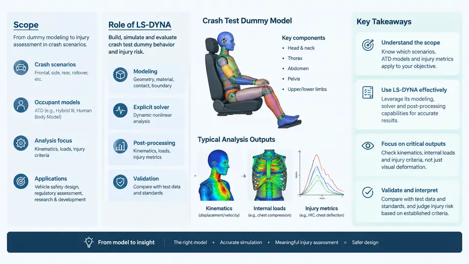
Crash test dummies — more precisely, Anthropomorphic Test Devices (ATDs) — are the physical instruments that translate a violent vehicle collision into a set of measurable, repeatable numbers. Those numbers, in turn, become the legal and engineering basis for occupant safety ratings, restraint system tuning, and regulatory compliance. This course is about reproducing that measurement chain inside a computer: building finite element models of ATDs, driving them through simulated crash events in LS-DYNA, and extracting injury-relevant quantities that can be compared against established criteria.
The scope of the course spans three connected domains. The first is ATD structural modeling: how the dummy's body regions — head, neck, thorax, abdomen, pelvis, and limbs — are discretized, what materials and connections represent their physical behavior, and how joints and instrumentation channels are represented. The second is crash simulation practice: setting up sled and full-vehicle models, applying boundary conditions and initial velocity, controlling contact, and managing the explicit time integration that LS-DYNA uses. The third is injury analysis: converting raw simulation output — accelerations, forces, moments, deflections — into injury criteria such as HIC, Nij, and chest deflection, and interpreting those values against threshold limits.
Why LS-DYNA Is the Standard Tool for This Work
LS-DYNA is an explicit finite element solver originally developed for high-velocity, large-deformation, transient problems. Crash events are exactly that: a 50 km/h frontal impact unfolds in roughly 100–150 ms, involves severe geometric nonlinearity, self-contact between body regions and restraints, and strain rates that change material response. An implicit solver would struggle with the contact complexity and convergence; LS-DYNA's explicit central-difference scheme advances the solution one small stable time step at a time without assembling a global stiffness matrix, which makes it robust for these events.
Equally important is the ecosystem around the solver. LS-DYNA ships with an extensive material library (including rate-dependent foams, viscoelastic rubbers, and elastic-plastic metals used in ATD components), mature contact algorithms (penalty-based surface-to-surface, tied, and single-surface contact), and a well-established dummy model portfolio. The LSTC/Ansys dummy models — THOR, Hybrid III 50th percentile male, EuroSID-2re, SID-IIs, and Q-series child dummies — are distributed as validated LS-DYNA keyword decks. Using these validated models is not a shortcut; it is the accepted industry practice, because the certification of a dummy model against physical calibration tests is a substantial undertaking in itself.
The Measurement Chain: From Physical Dummy to Injury Number
Understanding the course requires seeing the full signal chain clearly. A physical ATD contains accelerometers, load cells, and potentiometers. During a test, these transducers produce time histories. Those time histories are filtered (typically SAE J211 Class 180 for accelerations, Class 600 for forces and moments), then processed through injury criteria equations. The simulation must reproduce the same chain: the FE model's nodes and elements stand in for the transducers, and the same filtering and post-processing must be applied to the simulated signals.
The SVG below maps this chain and shows where LS-DYNA sits within it.
What You Will Be Able to Do
By the end of the course, you should be able to take a crash scenario description and produce a defensible simulation result. Concretely, that means:
- Select an appropriate validated ATD model for a given occupant position and test configuration, and justify the choice.
- Assemble a complete LS-DYNA keyword deck: dummy, restraint systems (belt, airbag), seat, and vehicle or sled environment.
- Define contact interfaces correctly, including belt-to-dummy, dummy-to-seat, and dummy-to-airbag interactions, and diagnose common contact instabilities.
- Set up and interpret the output requests needed for injury criteria — accelerometer locations, load cell cross-sections, and deflection measurements.
- Post-process time histories with the correct SAE J211 filter class and compute HIC, Nij, chest deflection, and other criteria.
- Judge whether a result is trustworthy by checking energy balance, hourglass energy, added mass, and time step stability.
A Worked Orientation Example
To make the scope concrete, consider a simplified driver-side frontal sled case. The input is a 50th percentile male Hybrid III dummy seated in a buck, restrained by a three-point belt with a 40 mm pretensioner stroke and a 250 kPa driver airbag. The sled pulse is a 50 km/h, 120 ms crash deceleration curve. The dummy model is the LSTC Hybrid III 50th percentile deck, positioned per the standard seating procedure.
The setup proceeds in a defined order. First, the dummy is positioned and its joints are set to the specified stiffness values; the belt is routed through the dummy's chest and pelvis using a seatbelt element formulation with slip rings at the retractor and buckle. Second, contact is defined: automatic surface-to-surface between belt and dummy, between dummy and seat, and between dummy and airbag. Third, the airbag is initialized with a mass flow rate curve derived from tank test data, and the sled is given the prescribed deceleration pulse via a boundary condition on the sled structure.
During the run, you monitor several things. The total energy should stay roughly constant (kinetic converting to internal and hourglass energy). Hourglass energy should remain below about 5% of internal energy; if it climbs, the dummy's foam elements are under-integrated and need refinement or a different formulation. The time step should be reported at the start; if it drops below roughly 1 microsecond, a small element is likely controlling the step and should be identified and fixed.
After the run, you extract the head center-of-gravity resultant acceleration, filter it at CFC 180, and compute HIC15. You extract the upper neck forces and moments, filter at CFC 600, and compute Nij. You extract chest deflection from the potentiometer node pair. A typical acceptable result for this configuration might show HIC15 in the range of 400–700, Nij below 1.0, and chest deflection under 50 mm — but these are illustrative ranges, not guarantees, and the actual values depend heavily on the pulse, belt geometry, and airbag tuning.
How the Course Is Organized
The chapters that follow build in a deliberate sequence. Early chapters establish the ATD as a physical and numerical object: its anatomy, its instrumentation, and the structure of a validated LS-DYNA dummy deck. Middle chapters move into simulation mechanics: contact, materials, boundary conditions, and solver controls specific to crash models. Later chapters address restraint interaction, occupant positioning, and the post-processing pipeline that turns raw output into injury criteria. The final chapters cover verification, validation, and the practical judgment required to defend a simulation result in a regulatory or engineering review.
Throughout, the emphasis is on the connection between what the model does numerically and what the physical dummy would do. A simulation that produces a plausible-looking number for the wrong reason is more dangerous than one that fails obviously, because it invites false confidence. The goal of this course is to give you the understanding needed to tell the difference.