1. Airbag system fundamentals
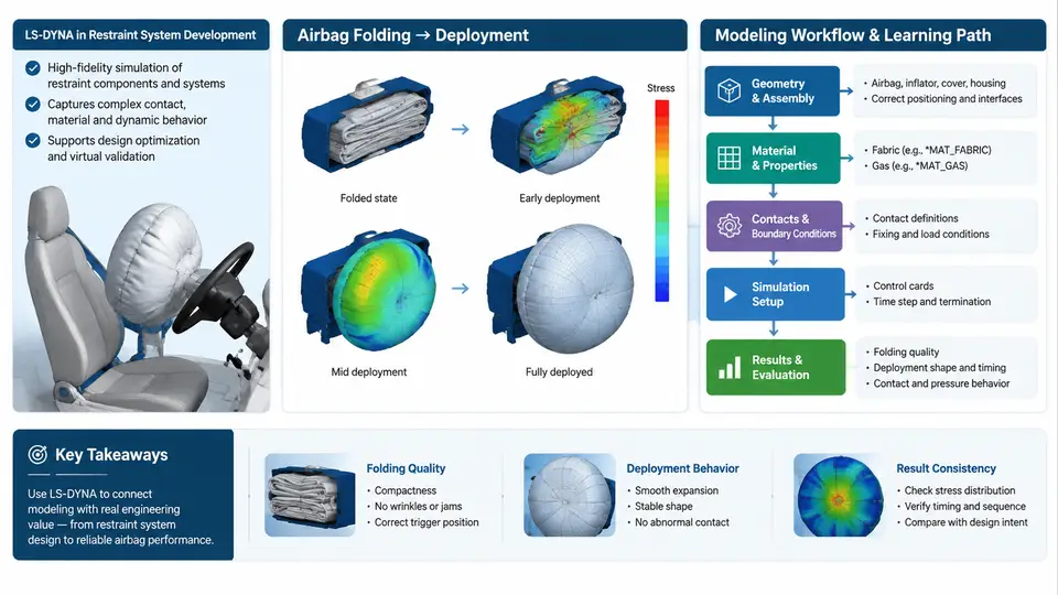
An airbag is not a single product but a restraint subsystem whose job is to decelerate an occupant's head and torso over a controlled distance and time. In LS-DYNA, every modeling decision — mesh density, material card, gas definition, contact stiffness — traces back to a physical characteristic of that subsystem. This chapter establishes the vocabulary and the physical relationships you will encode in the model: how restraint works, what bag architectures exist, how inflators deliver gas, and how the bag unfolds in space and time.
Occupant Restraint Principles
During a frontal impact the vehicle undergoes a large negative acceleration (deceleration) while the unrestrained occupant continues forward at roughly the pre-impact velocity. The restraint system's purpose is to limit the occupant's peak deceleration and to spread the loading over the strongest parts of the body. Three quantities govern the outcome:
- Ride-down distance — the distance the occupant travels forward relative to the vehicle before being brought to the vehicle's velocity. A larger ride-down distance reduces average deceleration for the same velocity change.
- Coupling time — the moment the occupant contacts the bag. Contacting a fully pressurized bag is harsh; contacting a partially inflated bag is soft but may bottom out.
- Pressure–area product — the force the bag can apply to the occupant, which must be high enough to arrest motion but low enough to avoid injury.
These three quantities are in direct conflict, and the inflator's mass-flow history is the primary tuning lever. In LS-DYNA this conflict appears as a trade-off between the *AIRBAG_ gas inflow curve and the venting definition: too much inflow with too little venting produces an over-stiff bag and high HIC; too little inflow produces bottom-out and contact with the steering wheel or instrument panel.
Bag Types and Their Modeling Implications
Airbags are classified by position, geometry, and deployment mechanism. The table below summarizes the types most commonly modeled in LS-DYNA and the modeling consequence of each.
| Bag type | Typical volume | Deployment mechanism | LS-DYNA modeling note |
|---|---|---|---|
| Driver frontal (DAB) | 55–70 L | Single inflator, folded into module | Uniform pressure (UP) or control-volume (CV) method is usually adequate |
| Passenger frontal (PAB) | 90–140 L | Single or dual inflator, top-mount or mid-mount | Larger volume; CV method with venting is standard |
| Side torso (SAB) | 12–20 L | Inflator in seat or door, rapid fill | Short fill time; fabric contact with seat structure matters |
| Curtain (CAB) | 25–40 L | Inflator at roof rail, fills along window | Elongated geometry; requires careful initial folding |
| Knee bolster (KAB) | 10–18 L | Small inflator, low pressure | Low fill rate; interaction with lower leg is critical |
The choice between the uniform pressure (UP) and control volume (CV) methods is the first major modeling decision. UP assumes the bag is a single pressure reservoir and is cheap but cannot capture pressure gradients during early deployment. CV divides the bag into chambers connected by fabric porosity and vents, and is required when the bag is large, when venting is asymmetric, or when the occupant contacts the bag before it is fully inflated.
Inflator Characteristics
An inflator is characterized by its mass flow rate and gas temperature as functions of time. Two inflator families dominate:
- Pyrotechnic — solid propellant burns to produce gas. Mass flow rises sharply and decays over 30–80 ms. Gas temperature is high (800–1200 K), so the ideal-gas assumption in the CV method must use an elevated temperature.
- Hybrid / stored gas — compressed gas is released by a pyrotechnic initiator. Mass flow is more controllable and the gas is cooler, which reduces fabric thermal loading.
In LS-DYNA the inflator is defined through *AIRBAG_ keywords. For the CV method, the essential inputs are the mass flow rate curve (LCID), the gas temperature, and the vent area. A representative pyrotechnic driver-side inflator might deliver a peak mass flow of 2.5–4.0 kg/s at roughly 10–15 ms, with total gas mass on the order of 40–60 g. These values are illustrative and must be replaced with the supplier's measured tank-test data for any real program.
Deployment Kinematics
Deployment is a sequence of distinct phases, and each phase stresses a different part of the model:
- Initiation (0–5 ms) — the inflator begins producing gas; the folded bag starts to unfold. Fabric-to-fabric contact dominates.
- Unfolding (5–20 ms) — the bag escapes the module and expands into the occupant space. Self-contact and module tear-seam behavior control the trajectory.
- Inflation (20–40 ms) — the bag reaches working pressure. Venting begins to regulate pressure.
- Occupant loading (40–80 ms) — the occupant contacts the bag; the bag deforms and vents gas. This is the phase that determines injury metrics.
The initial folded geometry is the single most influential input for the unfolding phase. LS-DYNA offers several folding utilities, but the practical approach is to import a supplier-provided folded mesh or to generate one with a scripted fold pattern (accordion, roll, or a combination). The fold pattern determines the bag's initial contact topology and therefore the early deployment trajectory.
What This Means for the Model
Every phase in the figure maps to a specific keyword block and a specific validation check. During initiation and unfolding, the critical checks are mesh quality (no inverted elements) and contact stability (no penetration through the module). During inflation, the check is that the predicted pressure–time curve matches the tank-test-derived expectation. During occupant loading, the check is that the bag does not bottom out and that the occupant's head and chest decelerations remain within the target envelope.
Reference Parameter Set for a Driver-Side Example
The following values are a reasonable starting point for a driver-side frontal bag study. They are illustrative and must be replaced with supplier data for any real analysis.
| Parameter | Value | Source / note |
|---|---|---|
| Bag volume (inflated) | 60 L | Nominal DAB |
| Peak mass flow | 3.0 kg/s | At ~12 ms, pyrotechnic |
| Total gas mass | 50 g | Integrated flow curve |
| Gas temperature | 1000 K | Ideal-gas assumption in CV method |
| Vent area | 2 × 500 mm² | Two vents, symmetric |
| Fill time to 95% volume | ~35 ms | Design target |
With these inputs, the CV method in LS-DYNA will produce a pressure–time history that rises to a peak near 30–40 ms and then decays as venting and occupant loading remove gas. If the simulated peak pressure is more than about 20% above the tank-test-derived expectation, check the vent area and the gas temperature first — these are the two inputs most often mis-specified.
The next chapter builds on this foundation by introducing the specific LS-DYNA keyword structure for airbag definition, including the *AIRBAG_ family and the folding utilities that generate the initial geometry discussed here.