1. Three-point seatbelt system overview
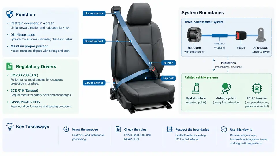
A three-point seatbelt is a single continuous webbing assembly that restrains an occupant at three load-bearing points: the lap anchor (outboard, near the floor or seat frame), the buckle/latch plate (inboard, at the occupant's hip), and the shoulder anchor (upper pillar or seat back). The retractor, typically mounted on the lower pillar or seat structure, stores the webbing and provides the retraction force that keeps the belt snug against the occupant. This geometry is the defining characteristic of the system: the lap portion controls pelvic motion, while the diagonal portion controls upper-torso motion, and the two paths share a single length of webbing through the latch plate.
Functionally, the three-point belt performs four distinct jobs that must be understood separately before any design work begins:
- Occupant retention — limiting forward excursion of the pelvis and torso during a crash so the occupant interacts with the airbag and interior surfaces in the intended sequence.
- Load distribution — spreading restraint forces over the strong skeletal structures (pelvis, rib cage, sternum) rather than concentrating them on soft tissue.
- Kinematic coupling — keeping the occupant in the designed seating position so that other restraint devices (frontal airbag, pretensioner, load limiter) can perform as validated.
- Comfort and usage promotion — providing low retraction force, smooth extraction, and acceptable pressure so that occupants actually wear the belt, which is the prerequisite for every other function.
These four functions are not independent. Increasing retraction force improves snugness and reduces slack but degrades comfort; increasing load-limiting travel reduces chest deflection but increases forward excursion and may compromise airbag interaction. The system engineer's task is to balance these trade-offs within the boundaries defined by regulation and vehicle packaging.
Regulatory Drivers
In most markets, the three-point belt is mandatory equipment, and its performance is governed by a combination of installation requirements and dynamic performance standards. The most widely referenced frameworks are:
| Framework | Scope | Key Implication for Design |
|---|---|---|
| FMVSS 208 | Occupant crash protection, US | Belt must be provided at all designated seating positions; performance evaluated with belted and unbelted dummies in frontal impact. |
| FMVSS 209 / 302 | Belt assembly performance, flammability | Defines webbing strength, hardware strength, and material burn behavior. |
| ECE R16 / R14 | Safety-belt and anchorages, UNECE | Anchor point location zones, strength requirements, and belt-type approval. |
| GB 14166 / GB 14167 | Belt assembly and anchorages, China | Harmonized with UNECE requirements for belt performance and anchor strength. |
| NCAP programs | Consumer rating, global | Drives load-limiter and pretensioner adoption beyond minimum legal requirements. |
Two regulatory concepts deserve emphasis. First, anchor point location is not a free design choice: ECE R14 and GB 14167 define permissible zones for the lap and shoulder anchors relative to the H-point and seat reference. A shoulder anchor placed too low or too far inboard will allow the diagonal to slip off the shoulder, while one placed too high may cause neck contact. Second, dynamic performance is evaluated with a specific dummy, impact speed, and barrier configuration. A belt that passes a 50 km/h rigid barrier test may still fail a 64 km/h offset deformable barrier test because the loading path and occupant kinematics differ. The system boundary must therefore be defined against the actual test matrix the vehicle program targets, not against a single regulation.
System Boundaries Within Occupant Restraint
The three-point belt is one subsystem within the broader occupant restraint system. Defining its boundary clearly prevents two common engineering errors: assuming the belt must solve problems that belong to the airbag, and assuming the airbag can compensate for a poorly performing belt.
The belt subsystem typically includes the following components and interfaces:
- Webbing — the load-bearing textile, with defined width, thickness, weave, and elongation characteristics.
- Retractor — includes the spool, locking mechanism (vehicle-sensitive and webbing-sensitive), and, where fitted, the load limiter (torsion bar or friction clutch) and pretensioner.
- Latch plate and buckle — the engagement interface, with defined insertion and release forces.
- Anchors and height adjuster — the structural attachment points and the shoulder height adjustment mechanism.
- Sensors and control interface — buckle switch, belt tension sensor, and the signal path to the airbag control unit (ACU).
What lies outside the belt boundary is equally important. The seat structure provides the anchor mounting stiffness; a compliant seat frame allows the belt anchors to move during loading, which changes the effective restraint geometry. The airbag provides supplementary torso and head restraint but is tuned to work with a belted occupant in a specific position. The steering column and knee bolster manage lower-extremity and pelvis motion. The belt cannot and should not attempt to replace these functions.
Practical Engineering Example: Defining the Boundary for a Front Seat
Consider a front outboard seating position in a mid-size passenger car targeting both FMVSS 208 (US) and ECE R16 (Europe). The belt subsystem engineer receives the following inputs from the vehicle program:
- Seat H-point coordinates and seat track travel range.
- B-pillar geometry and trim envelope.
- Target test matrix: 50 km/h rigid barrier (US), 64 km/h offset deformable barrier (Euro NCAP), and 32 km/h side pole.
- Airbag deployment timing and venting characteristics from the ACU team.
The first engineering decision is the shoulder anchor location. Using the ECE R14 zone, the anchor must fall within a defined area relative to the H-point. A practical starting point is to place the anchor approximately 450–550 mm above the H-point and 150–250 mm outboard, then verify with a 5th percentile female and 95th percentile male dummy that the diagonal passes over the mid-clavicle without neck contact. This is checked in CAE before any hardware is built.
The second decision is the retractor specification. For this vehicle, a load limiter with a two-stage torsion bar is selected: the first stage limits at approximately 4 kN for the initial 200 mm of webbing payout, then transitions to approximately 6 kN for the remainder. This balances chest deflection against forward excursion. A pyrotechnic pretensioner is specified to remove slack within 15 ms of the crash signal. These are example target values for a mid-size sedan; actual values must be validated by sled and vehicle testing.
The third decision is the interface definition. The belt team must agree with the seat team on anchor bolt torque, mounting bracket stiffness, and the maximum allowable anchor displacement under a 20 kN proof load. They must agree with the airbag team on the occupant position assumed at the time of airbag contact — typically 50–80 ms after impact — because the belt's load-limiting behavior directly affects that position. They must agree with the electrical team on the buckle switch signal format and the belt tension sensor range.
Key Takeaways for System Definition
Before detailed design begins, the following must be documented and agreed across the restraint team:
- Regulatory target matrix — which regulations and NCAP protocols apply, at what speeds, with which dummies, and with what pass/fail criteria.
- System boundary diagram — which components are inside the belt subsystem, which are interfaces, and which are external dependencies.
- Interface control documents — anchor locations, mounting stiffness, electrical signal definitions, and timing assumptions shared with airbag and seat teams.
- Performance targets — retraction force, extraction force, load limiter force levels, pretensioner stroke and timing, and webbing elongation.
- Verification plan — component-level tests (webbing tensile, buckle cycle, retractor lock), sled tests, and full vehicle tests, with clear entry and exit criteria for each stage.
With these defined, the three-point belt ceases to be a commodity part and becomes an engineered subsystem whose behavior can be predicted, validated, and traced back to the occupant protection targets it exists to serve.