4. Pyrotechnic pretensioner fundamentals
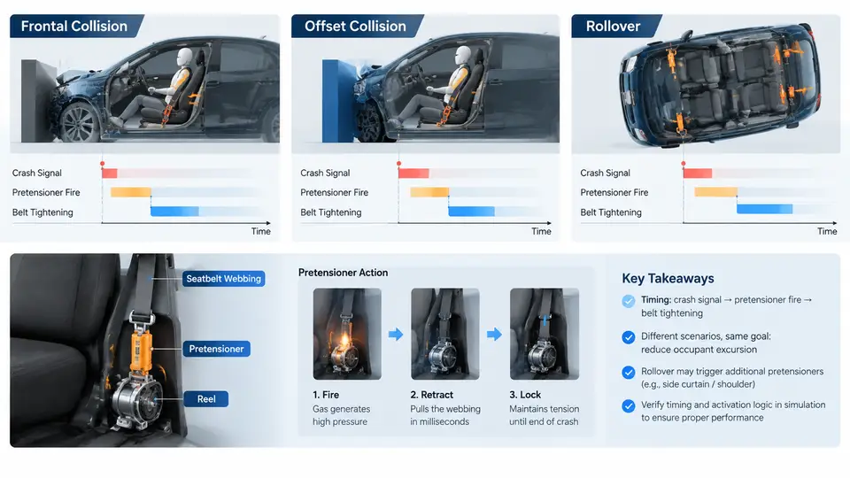
Pyrotechnic pretensioners are the fastest-acting restraint devices in a modern occupant protection system. Unlike motorized pretensioners, which rely on an electric motor and a reel mechanism, a pyrotechnic pretensioner converts stored chemical energy into mechanical work within a few milliseconds. The core of this conversion is the micro gas generator (MGG), a small sealed cartridge that produces a controlled volume of hot gas on command. Understanding the chemistry, the internal operation of the MGG, and the resulting pressure–time curve is essential for designing a pretensioner that pulls the belt webbing tightly against the occupant before the airbag and load limiter take over.
Gas Generator Chemistry
The gas generator in an MGG is a solid propellant, not a liquid or compressed gas. The most common formulation for automotive pretensioners is a sodium azide–free composition based on guanidine nitrate (CH₆N₄O₃) or a mixture of potassium nitrate (KNO₃) and a nitrogen-rich fuel such as 5-aminotetrazole. These formulations are chosen because they produce a high yield of nitrogen gas with low toxicity and relatively low flame temperature compared with older azide-based propellants.
A representative simplified reaction for a guanidine nitrate–based propellant is:
CH6N4O3 (s) → 2 N2 (g) + CO (g) + 2 H2O (g) + H2 (g) + heatIn practice, the reaction is not a single step. The propellant deflagrates — it burns from the surface inward rather than detonating — and the products include nitrogen, carbon monoxide, carbon dioxide, water vapor, and small amounts of hydrogen and nitrogen oxides. The oxidizer-to-fuel ratio is tuned so that the reaction is slightly fuel-rich, which keeps the flame temperature in the range of 1200–1800 K and limits the production of nitrogen oxides. The gas yield is typically 0.8–1.2 mol of gas per 100 g of propellant, and the heat of reaction is on the order of 2–4 MJ/kg.
The propellant is pressed into a cylindrical grain with a central perforation or a multi-perforated geometry. The burn rate follows Vieille's law:
r = a · P^nwhere r is the linear burn rate (mm/s), P is the chamber pressure (MPa), a is a temperature-dependent constant, and n is the pressure exponent. For typical pretensioner propellants, n lies between 0.3 and 0.7. A lower pressure exponent gives a more stable burn and reduces the sensitivity of the pressure–time curve to ambient temperature.
Micro Gas Generator Operation
The MGG is a miniature pyrotechnic actuator, typically 15–25 mm in diameter and 30–50 mm long. Its internal architecture consists of four functional layers: the initiator (squib), the booster charge, the main propellant grain, and the gas outlet or nozzle. The squib contains a bridge wire or semiconductor bridge (SCB) that heats up when a firing current of 1.2–2.0 A is applied for a few milliseconds. The heat ignites a small primary charge, which in turn ignites the booster, and the booster ignites the main propellant grain.
The entire sequence from firing current to full gas output takes 2–5 ms. The pressure inside the MGG combustion chamber rises rapidly, and the gas is expelled through a nozzle or a set of radial ports into the pretensioner cylinder. In a typical piston-type pretensioner, the gas pushes a piston that drives a rack or a cable, which rotates the belt reel and removes slack from the webbing. The stroke of the piston is usually 50–120 mm, and the belt retraction distance is 80–150 mm.
The MGG must be hermetically sealed to protect the propellant from moisture and to prevent gas leakage before deployment. The seal is typically a laser-welded or crimped metal-to-metal joint. The electrical interface is a two-pin connector with a defined resistance, usually 1.8–2.5 Ω, which allows the ECU to perform a continuity check.
Pressure–Time Characteristics
The pressure–time curve is the single most important performance signature of an MGG. It determines how quickly the pretensioner can retract the belt and how much force is applied to the occupant. A typical curve has four phases:
- Ignition delay (0–0.8 ms): The firing current heats the bridge wire, ignites the primary charge, and the flame propagates to the booster. Pressure is still near ambient.
- Pressure rise (0.8–2.0 ms): The main propellant ignites and burns rapidly. Chamber pressure rises from ambient to peak. The burn rate accelerates because r increases with P.
- Peak pressure (2.0–2.5 ms): The peak pressure typically reaches 25–40 MPa. At this point, the gas is flowing through the nozzle into the pretensioner cylinder, and the piston begins to move.
- Decay phase (2.5–5.0 ms): The propellant is consumed, and the gas expands into the cylinder. Pressure drops as the piston travels and the gas cools. The work done on the piston is the integral of the pressure–volume curve.
The area under the pressure–time curve, combined with the nozzle throat area, determines the mass flow rate of gas into the cylinder. The piston force is:
F = P_cylinder · A_pistonwhere A_piston is the piston cross-sectional area. For a 20 mm diameter piston, A_piston ≈ 314 mm². At a cylinder pressure of 10 MPa, the force is approximately 3.1 kN. This force accelerates the piston and the attached rack, which rotates the belt reel. The belt retraction force at the webbing is typically 1.5–3.0 kN, depending on the gear ratio and friction losses.
Practical Design Considerations
Several factors influence the pressure–time curve and must be controlled during design and validation:
- Ambient temperature: Propellant burn rate increases with temperature. At −35 °C, the ignition delay may increase by 0.2–0.4 ms, and the peak pressure may drop by 10–20%. At +85 °C, the peak pressure may rise by 10–15%. The MGG must be validated across the full automotive temperature range.
- Propellant grain geometry: A multi-perforated grain provides a more constant burn area and a flatter pressure plateau. A single-perforated grain produces a progressive burn, which may be desirable for a softer initial belt pull.
- Nozzle throat area: A smaller throat increases chamber pressure and burn rate but reduces mass flow. A larger throat reduces pressure but increases flow. The throat area is typically 2–8 mm².
- Filter and cooling: Some MGGs include a metallic mesh filter to trap particulates and cool the gas before it enters the cylinder. This reduces the risk of damaging the piston seal and lowers the gas temperature to 400–600 °C.
Example: Interpreting a Pressure–Time Trace
Suppose a bench test with a piezoelectric pressure sensor in a closed bomb (constant volume) yields the following data for a 1.0 g guanidine nitrate propellant:
| Time (ms) | Pressure (MPa) | Observation |
|---|---|---|
| 0.0 | 0.1 | Ambient; firing current applied |
| 0.5 | 0.8 | Booster ignition; pressure rising |
| 1.0 | 8.5 | Main propellant burning; rapid rise |
| 1.8 | 32.0 | Peak pressure reached |
| 2.5 | 18.0 | Decay begins; gas expanding |
| 4.0 | 4.0 | Piston stroke nearly complete |
| 5.0 | 1.2 | Residual pressure; gas cooling |
From this trace, the ignition delay is approximately 0.5 ms, the time to peak is 1.8 ms, and the total event duration is about 5 ms. The peak pressure of 32 MPa is within the typical range. If the peak pressure were below 20 MPa, the likely causes would be a weak booster, a cracked grain, or a partially blocked nozzle. If the peak pressure were above 45 MPa, the likely causes would be an over-charged propellant, a restricted nozzle, or an unusually high ambient temperature.
The pressure–time curve is not just a laboratory curiosity. It is the input to the pretensioner system model. In a simulation environment such as LS-DYNA or MADYMO, the MGG is represented by a pressure–volume curve or a gas mass flow function. The accuracy of this representation directly affects the predicted belt retraction distance, the occupant kinematics, and the overall restraint performance. Therefore, characterizing the MGG pressure–time curve under representative conditions is a prerequisite for any credible pretensioner simulation.