1. Pretensioner system overview
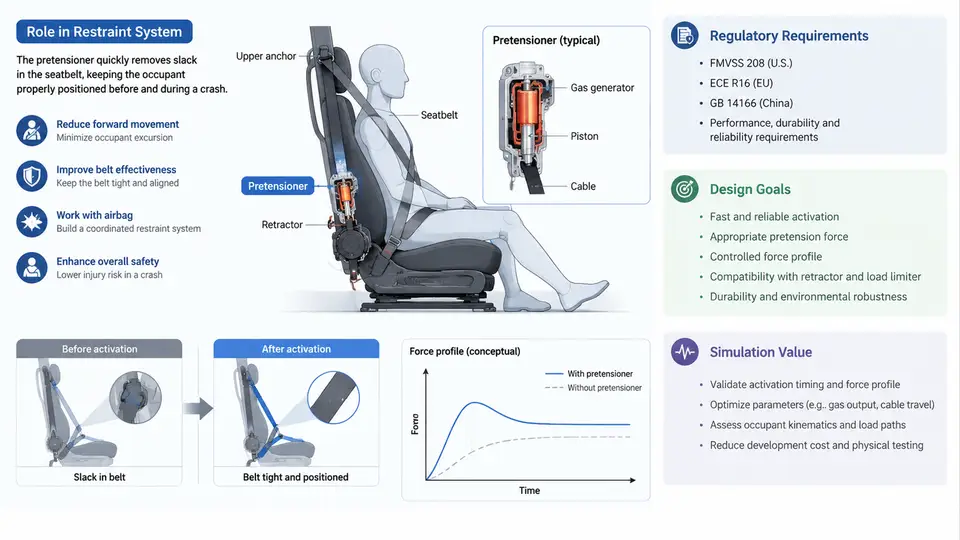
A seatbelt pretensioner is a pyrotechnic or electromechanical actuator that removes slack from the belt webbing within the first few milliseconds of a crash. Its purpose is not to restrain the occupant by itself, but to reposition the occupant into the correct posture before the load-limiting and energy-absorbing phases of the restraint system take over. Understanding why this matters requires looking at the crash event as a sequence of kinematic states, not as a single impact.
1.1 The Restraint Problem in Crash Kinematics
During a frontal impact, the vehicle undergoes rapid deceleration. The occupant, however, continues forward at approximately the pre-crash velocity until the belt engages. This velocity differential produces the "ride-down" distance — the distance the occupant travels relative to the vehicle before being coupled to the restraint system. A shorter ride-down distance means the occupant is coupled earlier, which reduces peak deceleration on the body and lowers injury risk.
Three kinematic phases define the restraint timeline:
- Phase 0 — Pre-crash (t < 0 ms): Occupant and vehicle move together. Belt webbing has 20–80 mm of slack depending on clothing, posture, and retractor lock position.
- Phase 1 — Slack removal (t ≈ 0–15 ms): Pretensioner fires, pulling webbing back through the buckle and retractor. Occupant begins to couple to the belt.
- Phase 2 — Ride-down and load limiting (t ≈ 15–80 ms): Belt force rises; load limiter (torsion bar or force-limiting retractor) caps belt force at a designed threshold, typically 2.5–4.5 kN at the shoulder.
Without a pretensioner, Phase 1 is dominated by free forward travel. The occupant may move 100–150 mm before belt tension develops, which increases the likelihood of contacting the steering wheel, instrument panel, or airbag before the airbag is fully inflated. The pretensioner compresses this phase to under 15 ms.
1.2 Where the Pretensioner Sits in the Seatbelt Assembly
A modern three-point seatbelt assembly integrates several subsystems. The pretensioner is one of them, and its placement determines its mechanical action:
| Subsystem | Function | Typical Actuation |
|---|---|---|
| Retractor pretensioner | Rotates spool to wind webbing | Pyrotechnic gas or mechanical spring |
| Buckle pretensioner | Pulls buckle downward, tensioning lap and shoulder belt | Pyrotechnic piston or cable drive |
| Anchor pretensioner | Moves outboard anchor to tighten lap belt | Pyrotechnic or motor-driven |
| Load limiter | Caps belt force during ride-down | Torsion bar, force-limiting retractor |
| Retractor locking mechanism | Locks spool after pretensioning | Inertia or web-sensitive lock |
In a typical B-segment vehicle, the retractor pretensioner and buckle pretensioner are often combined. The retractor pretensioner removes shoulder-belt slack, while the buckle pretensioner removes lap-belt slack. Together they can eliminate 60–120 mm of total webbing slack within 10–20 ms.
1.3 The Pretensioner Actuation Chain
The pretensioner does not fire independently. It is triggered by the airbag control unit (ACU) after crash detection. The signal chain is:
- Crash sensor input: Accelerometers and pressure sensors detect deceleration exceeding a calibrated threshold (e.g., 3–5 g for frontal impact).
- ACU decision logic: The ACU evaluates crash severity, occupant presence (via seat occupancy sensor), and belt buckle status.
- Firing command: A current pulse (typically 1.2–2.0 A for 0.5–2 ms) is sent to the pretensioner squib.
- Pyrotechnic initiation: The squib ignites a gas generator; gas pressure drives a piston or rotates a turbine.
- Mechanical action: The piston pulls a cable or rotates the retractor spool, winding webbing.
- Locking: After pretensioning, the retractor locks to prevent webbing payout.
The entire chain from sensor detection to full pretensioner stroke typically completes in 10–25 ms. This is why pretensioner timing is calibrated against the airbag deployment curve — the occupant must be pulled back before the airbag reaches full inflation.
1.4 Design Parameters and Their Influence
Pretensioner design is governed by several parameters that directly affect occupant kinematics:
- Stroke length: The distance the cable or piston travels. Typical values: 80–150 mm for retractor pretensioners, 60–100 mm for buckle pretensioners. Longer stroke removes more slack but requires more gas volume and packaging space.
- Actuation force: The force applied to the webbing. Peak force typically 1.5–3.0 kN. Too low and slack is not fully removed; too high and the occupant may be pulled into the seatback or experience belt-induced injury.
- Actuation time: Time from firing command to full stroke. Target: < 20 ms. This is dominated by gas generation rate and mechanical friction.
- Mass and packaging: Pretensioner mass adds to the retractor or buckle assembly. Typical added mass: 150–400 g per pretensioner.
These parameters are not independent. Increasing stroke length without increasing gas volume reduces actuation speed. Increasing force without a load limiter increases chest deflection risk. The design process therefore requires co-optimization with the load limiter and airbag.
1.5 Why Pretensioners Matter: Injury Metrics
The effectiveness of a pretensioner is measured through occupant injury criteria in crash tests. Common metrics include:
| Metric | Description | Typical Target |
|---|---|---|
| HIC (Head Injury Criterion) | Head acceleration integral over 15 ms window | < 700 (FMVSS 208) |
| Chest deflection | Rib cage compression relative to spine | < 50 mm (Euro NCAP) |
| Femur load | Axial force on femur | < 10 kN |
| Belt force | Shoulder belt tension | 2.5–4.5 kN (with load limiter) |
Studies and simulation results consistently show that adding a pretensioner reduces chest deflection by 15–30% and HIC by 10–20% in frontal impacts, primarily because the occupant is coupled to the belt earlier and the airbag interacts with a properly positioned occupant rather than one still moving forward.
1.6 System-Level View: Pretensioner + Load Limiter + Airbag
The pretensioner is not a standalone solution. It works as part of a coordinated restraint system. The interaction can be summarized as:
- Pretensioner: Removes slack, couples occupant early.
- Load limiter: Allows controlled webbing payout to cap belt force.
- Airbag: Provides a compliant surface for head and chest contact.
If the pretensioner fires too late, the occupant is already moving forward and the airbag may deploy into an out-of-position occupant. If it fires too early, the occupant may be pulled back into the seat before the airbag is ready, reducing the airbag's effectiveness. Calibration is therefore a trade-off between coupling time and airbag timing.
1.7 Practical Design Considerations
When designing or simulating a pretensioner, several practical factors must be addressed:
- Packaging: The pretensioner must fit within the retractor or buckle envelope. Retractor pretensioners are typically integrated into the retractor housing; buckle pretensioners are mounted on the seat frame or floor.
- Noise and vibration: Pyrotechnic actuation produces a sharp noise. The housing must contain the gas and debris. Mechanical pretensioners (spring or motor-driven) are quieter but slower.
- Environmental durability: The device must survive temperature cycling (−40°C to +85°C), humidity, and vibration without degrading. Pyrotechnic charges are sealed against moisture.
- Diagnostics: The ACU monitors pretensioner circuit resistance. A typical squib resistance is 1.8–2.5 Ω. Open or short circuits trigger a fault code.
- Reversibility: Pyrotechnic pretensioners are single-use. After deployment, the entire seatbelt assembly must be replaced. This is a service and cost consideration.
1.8 Summary
The pretensioner is a time-critical actuator that bridges the gap between crash detection and occupant coupling. Its design is governed by stroke length, actuation force, and actuation time, all of which must be co-optimized with the load limiter and airbag. In simulation, the pretensioner is represented as a force or displacement boundary condition on the belt system. Understanding its role in crash kinematics — specifically the reduction of ride-down distance and the early coupling of the occupant — is the foundation for all subsequent design and simulation work in this course.