1. Occupant restraint system architecture
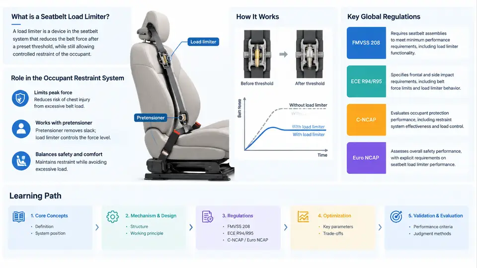
An occupant restraint system is not a collection of independent safety devices; it is a coordinated energy-management architecture. The seatbelt assembly, the load limiter, the pretensioner, and the airbag each handle a different portion of the occupant's kinetic energy during a crash, and they must be tuned to work as a single system. This chapter establishes the architectural view that every later design and optimization decision depends on.
The Seatbelt Assembly as the Primary Restraint
The three-point seatbelt remains the primary restraint because it acts on the occupant earlier and for longer than any airbag. Its main structural elements are:
- Webbing — typically polyester, roughly 48–50 mm wide, with controlled elongation (commonly 7–12% at a reference load) that contributes to ride-down.
- Retractor — houses the spool, the locking mechanism (vehicle-sensitive and web-sensitive), and, in modern systems, the load limiter and/or a torsion bar.
- Buckle and latch plate — transfer belt loads into the anchorages and the seat structure.
- Anchorage points — the retractor mounting, the buckle stalk anchor, and the outboard lower anchor, each with defined strength requirements.
The belt geometry determines how crash forces are distributed across the occupant's body. The lap belt should sit low across the pelvis, loading the iliac crests, while the shoulder belt crosses the mid-clavicle and sternum. A shoulder belt routed too far outboard allows the upper torso to roll out of the belt; one routed too close to the neck concentrates load on soft tissue. These geometric constraints are fixed early in the seat and body-in-white design, and they limit what a load limiter can later achieve.
Why a Load Limiter Exists
Without a load limiter, the belt behaves nearly as a rigid restraint once the retractor locks. The occupant's chest is then decelerated by whatever force the belt and the occupant's own compliance produce, and chest deflection can exceed injury thresholds. The load limiter deliberately introduces a controlled force plateau: above a threshold, the belt pays out additional webbing so that the force transmitted to the chest does not keep rising with occupant velocity.
The classic implementation is a torsion bar inside the retractor spool. When belt force reaches the design threshold, the torsion bar twists plastically and allows the spool to rotate, releasing webbing at a roughly constant force. The plateau force is set by the bar's diameter, material, and heat treatment. Typical passenger-car plateau forces fall in the range of approximately 3–6 kN at the retractor, though the value is always tuned to the specific vehicle, seat position, and occupant population.
Pretensioners: Removing Slack Before the Plateau
A pretensioner fires within the first few milliseconds of a detected crash and removes belt slack — the gap between the belt and the occupant's body, plus any spooled webbing. Two common types are the pyrotechnic buckle pretensioner and the retractor pretensioner. Some systems add a lap-belt pretensioner to pull the pelvis rearward.
Pretensioning matters because it determines when the occupant actually couples to the restraint. If slack is removed early, the belt engages the occupant sooner, the occupant's forward velocity at the moment of peak belt force is lower, and the load limiter's plateau can be reached more gradually. A system with a strong pretensioner and a well-matched load limiter can often use a lower plateau force than a system without pretensioning, because the occupant is already coupled and the belt is already taut when the plateau begins.
Airbag Integration
The frontal airbag is a supplementary restraint: it manages the head and upper torso after the belt has already begun decelerating the occupant. Its deployment timing, venting, and internal pressure are tuned to the belt's behavior. If the load limiter pays out too much webbing, the occupant travels further forward and may contact the airbag late, when it is already deflating; if it pays out too little, the chest is overloaded even though the airbag performs correctly.
Integration is therefore a timing and force-matching problem. The pretensioner fires first, the belt loads the occupant, the load limiter reaches its plateau, and the airbag — already inflated or inflating — catches the head as the torso continues forward. The airbag's vent size and the load limiter's plateau force are adjusted together during sled and full-vehicle testing.
System-Level Architecture
The diagram below shows the restraint system as a signal-and-force chain: crash detection triggers the pretensioner and airbag, while the belt path carries the mechanical load through the load limiter to the occupant.
Practical Integration Considerations
When tuning this architecture, engineers work with a small set of coupled parameters. The table below summarizes the main ones and their direction of influence.
| Parameter | Typical Range | Effect of Increasing |
|---|---|---|
| Load limiter plateau force | 3–6 kN | Higher chest load, less forward excursion |
| Pretensioner stroke | 40–80 mm | Earlier coupling, lower occupant velocity at plateau |
| Webbing elongation | 7–12% | More ride-down, more excursion |
| Airbag vent diameter | 25–45 mm | Faster deflation, softer catch, less late support |
These values are illustrative starting points for a mid-size passenger car, not measured results. Actual values are established through sled testing with instrumented ATDs (anthropomorphic test devices) and validated in full-vehicle crashes.
The architectural view established here — belt as primary restraint, pretensioner as coupling device, load limiter as force regulator, airbag as supplementary cushion — is the foundation for every subsequent chapter. Load limiter design is never an isolated exercise; it is always a negotiation between chest loading, occupant excursion, and the airbag's ability to fill the space that the belt allows.