1. Rear seat occupant protection engineerin
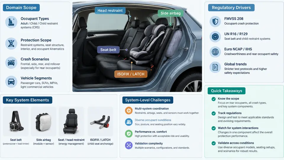
Rear seat occupant protection is the branch of vehicle safety engineering concerned with reducing injury risk for occupants seated behind the front row — in second-row bench or captain's chairs, and increasingly in third-row and rear-facing configurations. It spans restraint system design (seat belts, pretensioners, load limiters, airbags), seat structure and anchorage, child restraint system (CRS) interfaces, occupant packaging, and the sensing and deployment logic that decides when and how each device acts. What makes the domain distinctive is not any single component but the fact that the rear row sits at the intersection of several conflicting requirements: it must be comfortable and reconfigurable, it must carry the widest range of occupant sizes in the vehicle, and it must protect those occupants in crashes whose loading paths differ fundamentally from the front row.
What the Domain Actually Covers
A working definition of scope is useful before any design work begins. Rear seat occupant protection engineering includes:
- Restraint performance: belt geometry and routing, retractor behavior, pretensioning, force limiting, and — in some vehicles — rear inflatable belts or rear-row frontal airbags.
- Seat and anchorage integrity: seat frame strength, recliner and latch durability, floor and body anchorage stiffness, and the seat's behavior as a load path during frontal, side, and rear impacts.
- CRS compatibility: LATCH/ISOFIX lower anchorages, top tether anchorages, and the geometry that determines whether a real child seat installs correctly and stays correctly installed.
- Occupant classification and sensing: detecting whether a rear position is occupied, by what (adult, child, CRS, cargo), and adapting restraint output accordingly.
- Injury criteria and targets: translating dummy measurements into pass/fail judgments against regulatory and consumer-test thresholds.
The domain boundary matters because rear-row performance is frequently treated as a derivative of front-row design. In practice, the rear row has its own load paths, its own occupant population, and its own failure modes.
Regulatory and Consumer-Test Drivers
Rear seat protection is driven by a layered set of requirements rather than a single rule. The principal drivers are:
| Driver | Typical focus | Engineering consequence |
|---|---|---|
| FMVSS 208 (frontal) | Belted and unbelted frontal occupant protection, including rear positions in many configurations | Belt geometry, pretensioner/load-limiter tuning, seat strength |
| FMVSS 207 / 210 | Seat anchorage strength and belt anchorage strength | Floor and body structure, anchor reinforcement |
| FMVSS 213 / 225 | CRS performance and LATCH anchorage systems | Anchor location, spacing, and accessibility |
| FMVSS 214 / side impact | Side structure and interior padding | Rear side occupant excursion and contact |
| Consumer programs (e.g., US NCAP, Euro NCAP, IIHS) | Rear-seat dummy injury measures, CRS installation ease, rear-seat belt reminders | Performance targets often stricter than regulation |
The practical implication is that a rear seat design must satisfy a regulatory floor and then meet consumer-test targets that are frequently more demanding. A restraint that passes FMVSS 208 may still score poorly in a consumer rear-seat evaluation because the dummy's chest deflection or head excursion exceeds the program's threshold.
Why the Rear Row Is Harder Than It Looks
Three system-level challenges dominate rear seat protection work.
1. Occupant diversity. The rear row must protect a 6-year-old in a booster, a 95th-percentile adult male, a small female, and an infant in a rear-facing CRS — often in the same seat position across different trips. Belt geometry that fits a large adult may route poorly across a child's shoulder; a load limiter tuned for an adult may be too stiff for a small occupant. This is not a packaging inconvenience; it is a fundamental conflict that must be resolved through geometry, force management, or sensing.
2. Load path differences. Front-row occupants load the belt through a B-pillar and a seat structure designed around the driver. Rear-row occupants load through a C- or D-pillar, a seat that may fold, slide, or recline, and a floor structure that is often shared with cargo or fuel-system packaging. The result is different belt geometry, different anchor stiffness, and different occupant kinematics. A rear seat that simply reuses front-row restraint logic will not behave the same way.
3. Reconfigurability. Modern rear seats fold flat, slide fore-aft, recline, and in some cases rotate. Every configuration changes the belt routing, the anchorage position, and the occupant's distance to the interior. A restraint system must remain effective across all of them, or the vehicle must detect and compensate for the configuration.
From Requirements to Engineering Decisions
The practical work of this domain is translating the drivers above into concrete design decisions. Consider a representative rear bench with a 60/40 split, a sliding mechanism, and a center position that can accept a CRS. A typical engineering sequence looks like this:
- Define the occupant matrix. List the dummy sizes and CRS models that must be accommodated in each seating position. For a US-market vehicle this typically includes the Hybrid III 5th-percentile female, 50th-percentile male, 95th-percentile male, and a set of representative CRS.
- Establish belt geometry targets. Set the shoulder belt anchor height and fore-aft position so the belt crosses the clavicle for the adult population and does not ride up the neck or off the shoulder for smaller occupants. A common working target is a shoulder belt angle of roughly 20–30° from horizontal at the anchor for the 50th-percentile occupant, verified against the 5th-percentile.
- Select force management. Choose pretensioner stroke and load limiter force level. A load limiter in the range of 3–4 kN is a common starting point for rear-row adult occupants, but the value must be checked against child and small-occupant chest deflection.
- Verify anchorage stiffness. Confirm that the seat and floor anchorage do not allow excessive belt anchor displacement under load. Excessive compliance increases occupant excursion and can push head excursion past the target.
- Test and iterate. Run sled tests with the occupant matrix, record head excursion, chest deflection, and femur loads, and compare against the target envelope. Adjust geometry, force level, or structure as needed.
What Good Looks Like
A well-engineered rear seat protection system is not simply a scaled-down front row. It is a system that has been designed around the rear row's actual occupant population, its actual load paths, and its actual reconfiguration states. The measurable signs of success are consistent: head excursion within target for all dummies, chest deflection below the program threshold across the occupant matrix, CRS installation that is repeatable and unambiguous, and restraint behavior that remains predictable when the seat is folded, slid, or reclined. The rest of this course builds the methods — geometry, force management, sensing, and verification — that make those outcomes achievable.