4. Knee airbag system architecture
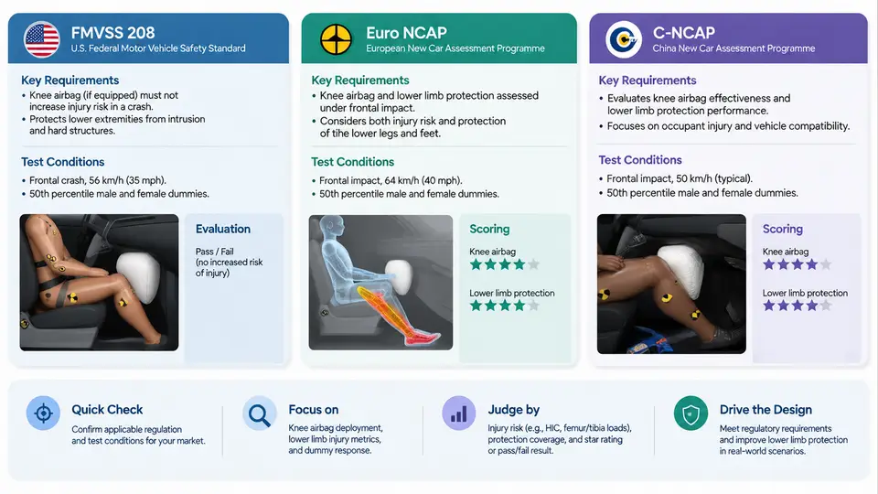
A knee airbag (KAB) is not simply a scaled-down frontal airbag. It is a short-stroke, high-pressure restraint whose job is to control the occupant's lower extremities and, indirectly, the pelvis and upper body through load-path coupling with the seat and instrument panel (IP). Because the cushion deploys into a very confined space — typically 150–350 mm of clearance between the knee and the IP or glovebox — the architecture must be compact, precisely aimed, and tightly integrated with surrounding structures. This section breaks the system into its four architectural pillars: module components, inflator selection, cushion geometry, and structural integration.
Module Components
A production KAB module is a self-contained subassembly that bolts to a carrier structure. The typical bill of materials includes:
- Housing / canister: stamped steel or injection-molded PA66-GF30, retaining the folded cushion and reacting inflator thrust. It defines the deployment chute and the exit aperture.
- Inflator: the gas source, mounted coaxially or offset within the housing.
- Cushion: a coated nylon 6.6 fabric (typically 420–630 dtex) with internal tethers and a heat shield at the inflator interface.
- Diffuser / manifold: distributes gas across the cushion inlet to avoid hot-spot burn-through and asymmetric fill.
- Retaining ring and fasteners: M6 or M8 studs, torque-controlled to 8–12 N·m depending on the carrier.
- Cover / trim flap: a tear-seam or hidden flap in the IP lower trim or steering-column shroud that opens predictably at a defined pressure.
- Electrical connector and pigtail: a 2-pin squib interface with a shorting clip, keyed to prevent cross-mating with other restraints.
The module is usually mounted either on the IP lower carrier (passenger side, below the glovebox) or on the steering column / column bracket (driver side). The choice of carrier determines the reaction structure and therefore the inflator output class.
Inflator Types
Three inflator families dominate KAB applications, and the selection is driven by packaging volume, output requirement, and cost:
| Type | Gas Source | Typical Output | Best Fit |
|---|---|---|---|
| Pyrotechnic | Solid propellant (e.g., guanidine nitrate) | High mass flow, short duration | Driver-side column KAB, small cushion |
| Hybrid | Propellant + stored compressed gas (Ar/He) | Moderate, cooler gas | Passenger IP KAB, larger cushion |
| Stored gas | Compressed gas only, pyrotechnic initiator | Low temperature, fast fill | Low-temperature / low-NOx requirements |
For a driver-side KAB, a pyrotechnic inflator with a 60–80 g propellant charge is common; it fills a 12–18 L cushion in roughly 20–30 ms. Passenger-side KABs, which must cover a wider knee spread, often use a hybrid inflator delivering 25–35 L. The inflator's burst pressure and mass flow rate curve must be matched to the cushion's vent area; an over-specified inflator will over-pressurize the cushion and increase knee loading, while an under-specified one will fail to reach the target internal pressure before occupant contact.
Cushion Geometry
KAB cushion geometry is defined by four parameters: deployed volume, frontal projected area, thickness (stroke), and tether configuration. A typical driver-side KAB deploys to 12–18 L with a projected area of 0.08–0.12 m² and a thickness of 120–180 mm. The cushion is intentionally shallow — it must arrest the knee over a short distance while distributing load across the femur and tibia.
Internal tethers are the primary tuning tool. A horizontal tether limits lateral expansion and keeps the cushion centered on the knee; a vertical tether controls the deployed thickness and prevents the cushion from wrapping around the leg. Vent holes (typically 2–4, 15–25 mm diameter) regulate internal pressure and energy absorption. The relationship between vent area and peak knee load is approximately inverse: doubling vent area can reduce peak load by 15–25%, but too much venting causes the cushion to bottom out against the IP.
Integration with Seat and Instrument Panel Structures
The KAB does not work in isolation. Its reaction forces must be grounded through the IP carrier or steering column, and its load path must be coordinated with the seat structure. Three integration issues dominate real-world development:
1. Reaction structure stiffness. The IP lower carrier must withstand the inflator thrust (typically 3–8 kN peak) without excessive deflection. A carrier that flexes more than 5 mm during deployment will misalign the cushion and reduce coverage. Finite element analysis (FEA) of the carrier under a 6 kN static load is a standard gate before hardware build.
2. Seat position and track travel. The KAB's coverage zone must account for the full seat track range (typically 200–240 mm fore-aft). At the forward-most position, the knee-to-IP clearance may drop to 150 mm; at the rear-most, it may exceed 350 mm. The cushion must deploy effectively across this range, which is why many OEMs use a dual-stage or adaptive inflator that adjusts output based on seat position and occupant size.
3. Trim flap and tear seam. The cover flap must open at a pressure low enough to not impede deployment but high enough to resist accidental opening. A typical tear seam is designed to rupture at 0.3–0.6 MPa. The flap hinge must remain attached to prevent the cover from becoming a projectile.
Practical Example: Driver-Side KAB Sizing Check
Consider a driver-side KAB with a pyrotechnic inflator (70 g propellant), a 15 L cushion, and a vent area of 3 × 20 mm. The target peak knee load is below 4.0 kN (a common internal target, not a regulatory limit). Using a simplified closed-vessel model:
Given:
  Inflator mass flow: ~1.2 kg/s peak
  Cushion volume: 15 L = 0.015 m³
  Vent area: 3 × π × (0.01)² = 9.42e-4 m²
  Gas constant (approx): R = 300 J/(kg·K)
  Temperature: 800 K

Estimate peak pressure:
  P ≈ (m_dot × R × T) / (V_dot + A_vent × v_exit)
  With V_dot ≈ 0.015 / 0.025 = 0.6 m³/s
  and v_exit ≈ 200 m/s
  P ≈ (1.2 × 300 × 800) / (0.6 + 9.42e-4 × 200)
  P ≈ 288000 / (0.6 + 0.188) ≈ 365 kPa

This is within the typical 250–450 kPa range for a driver KAB.
If peak knee load exceeds target, increase vent area by 20% and re-check.
This calculation is a first-order estimate only; final validation requires sled testing with a Hybrid III 50th percentile male dummy and a THOR or BioRID for rear-seat configurations. The key takeaway is that inflator output, cushion volume, and vent area form a coupled system — changing one requires re-checking the others.
Key Architectural Trade-offs
- Packaging vs. coverage: A larger cushion improves coverage but requires more IP volume and a larger inflator.
- Cost vs. adaptivity: Dual-stage inflators add cost but improve performance across seat positions.
- Weight vs. stiffness: A stiffer carrier adds mass; a lighter carrier may deflect excessively.
- Deployment speed vs. occupant safety: Faster fill reduces out-of-position risk but increases peak load.
These trade-offs are resolved through iterative CAE and sled testing, with the architecture frozen only after the module, inflator, cushion, and integration interfaces are all validated together.