4. Airbag fundamentals
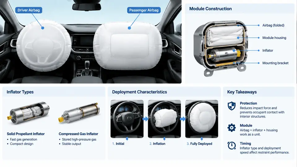
Frontal airbags are the most widely deployed supplemental restraint in modern vehicles, yet their apparent simplicity hides a tightly engineered chain of sensing, decision, and pyrotechnic events. This chapter examines the driver and passenger frontal airbag as physical assemblies: how each module is constructed, which inflator technologies are used, and how deployment characteristics are shaped by gas generation, cushion geometry, and venting. The goal is to give you the vocabulary and mental model needed to reason about airbag performance before we move into optimization.
4.1 The Frontal Airbag as a Supplemental Restraint
An airbag is supplemental because it is designed to work with the seatbelt, not replace it. The seatbelt provides the primary restraint by coupling the occupant to the vehicle structure early in a crash. The airbag then manages the remaining kinetic energy by distributing load over a larger area and limiting peak chest and head acceleration. Two consequences follow directly from this division of labor:
- An unbelted occupant travels further before contacting the cushion, so the airbag must be larger and inflated earlier to be effective.
- An occupant positioned too close to the module (out-of-position, OOP) can be struck by the deploying cushion itself, which is why suppression logic and low-risk deployment strategies exist.
Both driver and passenger frontal airbags deploy in roughly the same crash severity window — typically a frontal delta-v above approximately 15–25 km/h against a rigid barrier, depending on calibration — but their physical implementations differ substantially because of packaging space and occupant distance.
4.2 Driver Airbag Module Construction
The driver airbag module is mounted in the steering wheel hub and typically consists of five functional layers:
- Cover (trim pad): A molded thermoplastic cover with a hidden tear seam. The seam is the weakest path and defines how the cover splits — usually an H-pattern or a single linear seam. Cover material must remain ductile at −35 °C and not fragment at +85 °C.
- Cushion: A woven nylon 6.6 fabric, commonly 470–630 dtex, coated on one side with silicone or neoprene to control permeability. The cushion is folded in a specific pattern (e.g., accordion, reversed fold, or a combination) so it unfolds outward rather than sideways.
- Inflator: A cylindrical or disc-shaped gas generator seated in a metal housing or reaction can.
- Retainer ring and housing: A steel ring clamps the cushion throat to the housing and reacts the inflator thrust load.
- Electrical interface: A squib connector with a shorting clip that prevents accidental firing during handling.
A typical driver cushion volume is 60–75 liters for a mid-size vehicle, and the module must fit within a steering wheel hub roughly 180–220 mm in diameter. That packaging constraint is the main reason driver inflators are compact and why the cushion fold pattern is so carefully controlled.
4.3 Passenger Airbag Module Construction
The passenger frontal airbag sits behind the instrument panel on the passenger side, usually above the glovebox. Its construction differs in three important ways:
- Larger cushion: 90–140 liters, because the occupant is further from the module and the cushion must span a wider area.
- Chute or deployment door: A separate door with hinges and a tear seam, often with a tether, guides the cushion upward along the windshield rather than into the occupant's knees.
- Reaction can: A stamped steel or aluminum can that holds the inflator and directs gas into the cushion throat; it also anchors the module to the cross-car beam.
Because the passenger cushion is larger, it generally requires a higher mass flow rate from the inflator, and the deployment door geometry strongly influences how the cushion interacts with the windshield and the occupant.
4.4 Inflator Types
Three inflator families dominate frontal applications. The choice depends on required gas output, packaging, cost, and thermal management.
| Type | Principle | Typical Use | Key Characteristics |
|---|---|---|---|
| Pyrotechnic | Solid propellant (e.g., sodium azide historically, now guanidine nitrate-based) burns to generate gas | Driver modules, some passenger modules | Fast onset, high gas temperature, requires filtration and cooling |
| Hybrid | Pyrotechnic charge heats and releases stored compressed gas (argon/helium) | Passenger modules, side airbags | Lower flame temperature, more gas per unit mass, larger package |
| Stored gas | Compressed gas released by a pyrotechnic valve | Rare in frontal; used in some side and pedestrian systems | Cold gas, no combustion residue, pressure vessel packaging |
Modern frontal inflators are almost always pyrotechnic or hybrid. A representative driver inflator contains 40–80 g of propellant and produces 60–80 liters of gas at standard conditions within 30–50 ms. Passenger hybrid inflators may combine 20–40 g of propellant with a stored gas charge to reach 100–140 liters.
4.5 Deployment Characteristics
Deployment is a sequence of timed events, not a single instant. The figure below shows the signal and gas path from crash detection through cushion pressurization.
Three parameters dominate the deployment characteristic:
- Time to first gas (TTFG): The delay between the squib current pulse and the first measurable pressure rise. For pyrotechnic inflators this is typically 1–3 ms.
- Mass flow rate: The rate at which gas enters the cushion, often expressed in grams per millisecond. A driver inflator might deliver 2–4 g/ms during the first 20 ms.
- Vent area: The total effective open area of vent holes plus fabric permeability. Venting controls the pressure decay after peak and prevents the cushion from becoming too stiff.
These parameters are tuned together. Increasing mass flow rate inflates the cushion faster but raises peak pressure and can increase occupant loading. Increasing vent area reduces peak pressure but may allow the cushion to bottom out during a high-severity event. The calibration task is to find the combination that minimizes injury criteria such as HIC and chest deflection across the required test matrix.
4.6 Practical Example: Reading a Deployment Pressure Trace
Suppose a driver airbag is tested on a static deployment rig at +23 °C. The recorded cushion pressure rises from 0 to a peak of approximately 180 kPa at 28 ms, then decays to 40 kPa by 80 ms. The following observations are typical:
- A peak earlier than 25 ms suggests a fast inflator or a small cushion volume.
- A slow decay after peak suggests insufficient venting or low fabric permeability.
- A secondary pressure rise after 60 ms may indicate the cushion is rebounding or that the occupant is compressing the cushion.
If the same module is tested at −35 °C, the peak pressure typically drops by 10–20% and occurs later because propellant burn rate decreases. At +85 °C, the opposite occurs. This temperature sensitivity is a key reason inflator propellant formulations and grain geometry are carefully selected.
4.7 Failure Modes and Diagnostics
Frontal airbag systems are monitored continuously by the airbag ECU. Common fault indications include:
- Open squib circuit: Resistance above the expected 1.7–2.5 Ω window; often caused by a disconnected connector or a broken clock spring in the steering wheel.
- Short to ground or battery: Resistance below the lower threshold; can be caused by chafed wiring or moisture in a connector.
- Low inflator output: Not directly measurable by the ECU; detected only through deployment testing or post-deployment inspection of the cushion and inflator residue.
After a deployment, the module must be replaced as a complete assembly. The inflator, cushion, cover, and housing are all single-use components. Reusing any part of a deployed module is unsafe and is not permitted by any OEM service procedure.
4.8 Key Takeaways
- Driver and passenger frontal airbags share the same sensing and firing chain but differ in cushion volume, module packaging, and inflator output.
- Pyrotechnic and hybrid inflators are the dominant types; the choice depends on gas output, packaging, and thermal requirements.
- Deployment characteristics are governed by time to first gas, mass flow rate, and vent area — all tuned together to meet injury criteria.
- Temperature strongly affects inflator output; always interpret pressure traces with test temperature and cushion volume in mind.
- Airbag modules are single-use assemblies; fault diagnosis focuses on squib circuit integrity, not on measuring inflator performance directly.