1. Occupant restraint system architecture
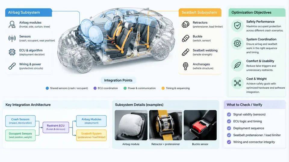
A modern occupant restraint system is not a single device but a coordinated network of sensing, decision, and actuation subsystems. The airbag and the seatbelt are the two primary energy-management paths, and their performance is only as good as the integration between them. This chapter establishes the architectural vocabulary and the optimization logic that the rest of the course builds on.
Two Subsystems, One Occupant
The seatbelt subsystem is the continuous restraint. It consists of the webbing, retractor, buckle, anchor points, and — in modern vehicles — a pretensioner and a load limiter. Its job is to couple the occupant to the seat early in a crash, then manage the deceleration energy over the longest possible distance and time.
The airbag subsystem is the discrete restraint. It includes the inflator, the cushion, the module housing, and the venting strategy. Its job is to provide a supplementary, distributed pressure surface that reduces peak contact forces on the head, chest, and pelvis during the brief window when the belt alone cannot control occupant kinematics.
The word "supplementary" is deliberate. An airbag without a fastened belt is not a restraint system; it is a hazard. The architecture assumes belt-first coupling, with the airbag filling the gap between the occupant and the interior structure.
Integration Points That Define Behavior
Integration is where most real-world performance is won or lost. The critical interfaces are:
- Timing interface: pretensioner fire time, airbag inflator trigger time, and belt load-limiter slip onset must be sequenced so the occupant is coupled before the cushion is fully pressurized.
- Geometry interface: seat position, steering column travel, and cushion deployment path determine whether the airbag contacts the occupant or the occupant "misses" the cushion.
- Force interface: belt load-limiter force and airbag venting pressure together set the total restraint force curve. If both are too stiff, chest deflection rises; if both are too soft, occupant excursion increases.
- Sensing interface: crash severity, occupant classification, and buckle status feed the Restraint Control Module (RCM), which selects the deployment threshold and the airbag stage.
Optimization Objectives
Optimization in this domain is multi-objective and constrained. The primary objectives are:
- Minimize occupant injury metrics — HIC15 for head, chest deflection and chest acceleration (3 ms clip) for thorax, and femur load for lower extremities.
- Maintain out-of-position (OOP) safety — a deploying airbag must not injure a small occupant seated too close to the module.
- Preserve belt effectiveness — pretensioner and load limiter must not compromise the belt's ability to keep the occupant in the seat.
- Meet regulatory and rating targets — FMVSS 208, Euro NCAP, and C-NCAP thresholds define the pass/fail envelope.
These objectives conflict. A stiffer belt reduces excursion but raises chest deflection. A larger airbag reduces head acceleration but increases OOP risk. Optimization is therefore a trade study, not a single-variable tuning exercise.
Architecture at a Glance
The diagram below shows the signal and energy flow from crash event to occupant response, with the key integration points marked.
From Architecture to Tuning: A Worked Example
Consider a frontal 56 km/h rigid barrier test with a 50th-percentile male ATD. The baseline calibration uses a single-stage inflator, a 4 kN belt load limiter, and a pretensioner fired at 12 ms after impact. The observed chest deflection is 58 mm — above the 50 mm target — while HIC15 is 620, comfortably within limits.
The engineering question is: which parameter to change? Increasing load-limiter force would reduce chest deflection but raise belt-induced chest compression. The better move is usually to advance pretensioner timing and soften the airbag vent, letting the belt couple earlier while the cushion absorbs more head energy. A typical iteration might shift pretensioner fire to 8 ms and increase vent area by 15%, then re-run the sled test.
Expected observable changes: chest deflection drops toward 48–52 mm, HIC15 rises slightly to 650–680, and occupant excursion (measured as head forward displacement) decreases by 20–30 mm. If chest deflection does not respond, the likely cause is that the pretensioner is firing after the occupant has already begun forward motion — check the belt force trace for a late rise.
Key Architectural Decisions
| Decision | Typical Options | Primary Trade-off |
|---|---|---|
| Inflator type | Pyrotechnic, hybrid, cold gas | Deployment speed vs. OOP risk and cost |
| Load limiter | Fixed torsion bar, adaptive force limiter | Chest protection vs. excursion control |
| Pretensioner | Pyrotechnic buckle, motor retractor | Coupling speed vs. reversibility and comfort |
| Airbag staging | Single-stage, dual-stage, adaptive vent | Severity matching vs. system complexity |
Each decision propagates through the integration points. A dual-stage inflator, for example, allows the RCM to fire only the first stage in a low-severity crash, reducing OOP risk without sacrificing high-severity performance. But it also requires a more sophisticated sensing algorithm and a more complex wiring harness.
What "Optimized" Means in Practice
An optimized restraint system is not the one with the lowest single injury metric. It is the one that satisfies all regulatory and rating targets across the widest range of crash severities, occupant sizes, and seating positions, while remaining manufacturable and cost-effective. The rest of this course examines each subsystem in detail, then returns to the integration problem with simulation and test methods that let you quantify these trade-offs rather than guess at them.