4. Airbag cushion design fundamentals
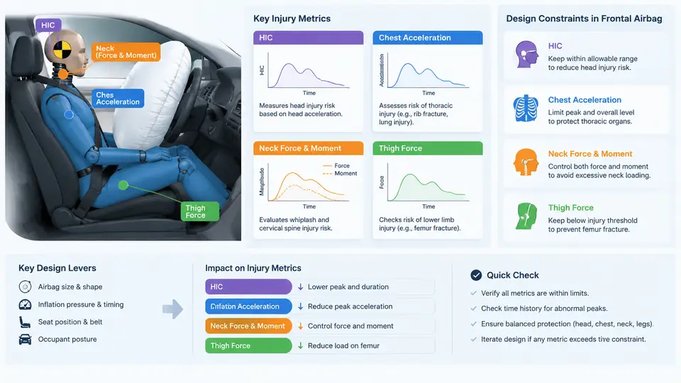
The inflatable cushion is the only part of the frontal airbag system that the occupant actually contacts, so its geometry and gas-handling behavior determine whether the restraint is gentle, aggressive, or simply ineffective. This chapter treats the cushion as an engineering pressure vessel with a controlled leak: shape and volume set the available stroke, seam patterns define how the fabric panels assemble into that shape, tethers constrain the inflated form, and the vent hole governs the pressure–time history that the occupant feels.
Shape and Volume: The Occupant's Available Stroke
For a driver airbag, the cushion is a shallow, roughly circular bag mounted on the steering-wheel hub, typically 600–750 mm in diameter when fully inflated and 250–350 mm deep. The passenger cushion is much larger and asymmetric: it must span from the instrument panel to the occupant across a wider seating range, so a typical passenger bag inflates to 700–900 mm wide, 500–700 mm tall, and 400–600 mm deep. These are representative design targets, not universal values; the actual numbers come from the occupant packaging study.
Volume follows from shape and the required fill pressure. A driver cushion commonly holds 60–90 L at peak inflation, while a passenger cushion holds 100–150 L. The governing relationship is the ideal-gas form applied to the inflator output:
P_cushion(t) ≈ (n(t) · R · T) / V(t)

n(t)  = moles of gas delivered by the inflator up to time t
V(t)  = instantaneous cushion volume as it unfolds
T     = gas temperature (cooling as it mixes with ambient air)
Because V(t) grows rapidly during deployment, peak pressure occurs early, before the bag is fully unfolded. If the cushion is too small, pressure spikes and the bag feels like a punch; if it is too large, the bag may not develop enough pressure to arrest the occupant before bottoming out against the module. Volume is therefore tuned together with vent area, not in isolation.
Seam Patterns and Panel Construction
A cushion is not a single molded balloon. It is cut from coated fabric — typically 420–630 denier nylon 6.6 with a silicone or neoprene coating — and joined along seams. The seam pattern determines the three-dimensional inflated shape from two-dimensional panels.
- Driver cushion: usually two circular face panels joined around the perimeter, with a central mounting ring at the hub. Some designs add a shallow cylindrical side band to increase depth without increasing diameter.
- Passenger cushion: a "top and bottom" or "two-panel plus gusset" layout, where a perimeter gusset controls depth and the face panels control the frontal profile. Asymmetric panels let the bag reach the outboard and inboard seating positions differently.
Seam type matters as much as seam location. A sewn seam with lockstitch or chainstitch is common, but high-load seams may use a woven or one-piece woven (OPW) construction, where the bag is woven as a single piece and only the outer contour is cut. OPW eliminates sewn seams in the high-pressure region and reduces the risk of seam rupture, but it constrains the achievable shape. Seam allowance, stitch density (typically 4–6 stitches per cm), and thread tensile strength must all be specified, because a seam that fails at 200 kPa effectively removes the restraint.
Tethers: Controlling Shape and Occupant Interaction
Tethers are internal fabric straps that pull the cushion into a controlled shape. They serve three purposes: limiting depth so the bag does not over-extend into the occupant, shaping the bag to match the steering wheel or instrument panel contour, and controlling how the bag unfolds so it does not slap the occupant during the early deployment phase.
Common tether configurations include:
- Depth-limiting tethers: run from the front face to the mounting plate, capping maximum depth (e.g., 280 mm for a driver bag).
- Profile tethers: run across the face to flatten or dish the center, preventing a "balloon" that concentrates force at the sternum.
- Fold-control tethers: release in a defined sequence so the bag unfolds outward and downward before contacting the occupant.
Tether length is a direct design variable. Shortening a depth tether by 20 mm reduces inflated depth by roughly the same amount and raises peak pressure because the same gas fills a smaller volume. Tether anchor points must be reinforced; a tether that tears free at its stitch line changes the bag's shape mid-deployment and can produce unpredictable occupant loading.
Vent Hole Sizing: The Pressure Relief Valve
The vent hole is the primary control on the pressure–time curve after peak inflation. It allows gas to escape so the cushion can absorb energy by controlled compression rather than acting as a rigid surface. Vent area is usually expressed as one or more circular holes, commonly 25–45 mm diameter for a driver bag, and the total effective vent area is what matters.
The venting behavior can be approximated with an orifice flow relation:
ṁ_vent = C_d · A_vent · sqrt( 2 · ρ · ΔP )

C_d     ≈ 0.6–0.8 (discharge coefficient, depends on hole geometry and fabric)
A_vent  = total vent area (m²)
ρ       = gas density inside the cushion
ΔP      = P_cushion − P_ambient
If the vent is too small, the cushion stays pressurized and the occupant decelerates too abruptly. If it is too large, the bag deflates before the occupant's energy is absorbed, and the occupant may contact the steering wheel or instrument panel. Vent sizing is therefore validated against the occupant's kinetic energy at the design impact speed, not chosen by rule of thumb.
How the Variables Interact
Shape, volume, seams, tethers, and venting are not independent. A deeper bag needs more gas, which raises peak pressure unless the vent is enlarged. A tighter tether reduces volume, which raises pressure unless the inflator output is reduced. A larger vent lowers pressure but also shortens the time the cushion can absorb energy. The design process is therefore iterative: set the occupant packaging targets, choose a preliminary shape and volume, define seam and tether layout, then tune vent area against the simulated pressure–time and occupant response.
Practical Sizing Workflow
A reproducible first-pass sizing exercise for a driver cushion at a 50 km/h frontal impact target might proceed as follows. Assume an occupant mass of 78 kg, a desired ride-down distance of 250 mm, and an inflator that delivers 2.5 moles of gas in 30 ms. The required average cushion pressure to absorb the occupant's kinetic energy over that stroke is approximately:
E_occupant = ½ · m · v²
           = ½ · 78 · (13.9)²  ≈ 7.5 kJ

F_avg = E / d = 7500 / 0.25 ≈ 30 kN
A_contact ≈ 0.12 m² (driver bag contact patch)
P_avg ≈ F / A ≈ 30,000 / 0.12 ≈ 250 kPa
This 250 kPa is an average over the stroke; peak pressure will be higher. The vent area is then selected so that the pressure decays from its peak toward this average within the ride-down time. Using the orifice relation with C_d = 0.7, ρ ≈ 1.2 kg/m³, and ΔP ≈ 150 kPa, a 35 mm diameter hole gives:
A_vent = π · (0.035/2)² ≈ 9.6 × 10⁻⁴ m²
ṁ_vent ≈ 0.7 · 9.6e-4 · sqrt(2 · 1.2 · 150000) ≈ 0.7 · 9.6e-4 · 600 ≈ 0.40 kg/s
That mass flow rate, integrated over the 30–50 ms ride-down window, removes roughly 12–20 g of gas — enough to bring the pressure down meaningfully without collapsing the bag. These numbers are illustrative and must be confirmed by simulation and sled testing; they are not a substitute for validated CAE results.
Key Takeaways
- Shape and volume set the available stroke; they are tuned together with vent area, not independently.
- Seam patterns translate 2D panels into the 3D inflated form; seam type and stitch density are structural variables.
- Tethers control depth, profile, and fold sequence; shortening a tether raises pressure by reducing volume.
- Vent hole sizing governs the pressure–time curve and must be validated against occupant energy, not chosen by rule of thumb alone.
- All five variables interact — change one and the others must be re-checked in simulation and, ultimately, in sled testing.