1. Frontal airbag system architecture
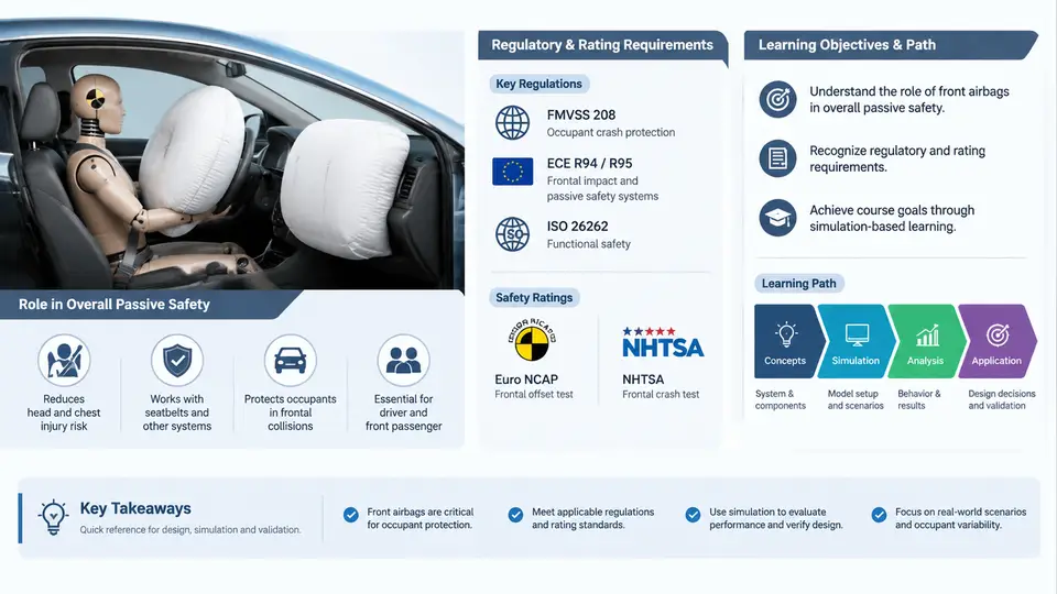
A frontal airbag system is not a single product but a distributed restraint subsystem whose behavior is decided in the first 30–50 ms of a crash. Understanding its architecture means understanding four cooperating layers: the airbag modules (driver and passenger), the inflators that generate gas, the crash sensors that detect the event, and the Airbag Control Unit (ECU) that arbitrates deployment. This chapter maps those layers, their interfaces, and the design constraints that bind them together inside the vehicle restraint system.
1. System-Level View of the Frontal Restraint Chain
The frontal restraint system is a closed-loop signal chain with a one-shot actuation path. Crash deceleration is sensed, filtered, and classified by the ECU; if the classification crosses a calibrated threshold, the ECU fires the inflator squib, which rapidly generates gas to fill the cushion. The cushion then interacts with the occupant, and the occupant's motion is managed together with the seat belt load limiter and pretensioner. The airbag is therefore a supplemental restraint — the belt remains the primary energy-absorbing device.
Three architectural decisions dominate the design:
- Deployment decision authority — the ECU alone decides; sensors only report.
- Redundancy — at least two independent sensing paths must agree before firing.
- Occupant classification — passenger-side deployment is suppressed or derated based on seat occupancy and position.
2. Driver and Passenger Airbag Modules
The driver airbag module (DAB) is mounted on the steering-wheel hub. Its cushion is folded in a specific pattern — often a "petal" or "star" fold — so that it unfolds radially and rearward toward the driver's chest and head. The module includes the cushion, the inflator, a metal retainer ring, and the horn/trim cover with a tear seam. The tear seam is engineered to split at a defined pressure, typically 200–400 kPa internal cushion pressure during the first few milliseconds.
The passenger airbag module (PAB) is larger and mounted behind the instrument panel. Because the windshield and IP act as reaction surfaces, the PAB cushion is designed to deploy upward and rearward along the windshield, then fold down toward the occupant. A fabric chute or deployment ramp guides the cushion through the IP opening and prevents it from snagging on the panel edge. PAB cushions are typically 60–120 L in volume, compared with 35–60 L for a driver cushion.
Both modules share the same functional interfaces: a mechanical mount to the vehicle structure, an electrical connector to the ECU squib circuit, and a defined deployment envelope that must remain clear of other components throughout the cushion's inflation path.
3. Inflators: Chemistry, Types, and Output
The inflator converts a small electrical firing pulse into a large volume of gas within roughly 20–40 ms. Three architectures are common in frontal systems:
| Type | Principle | Typical Use | Notes |
|---|---|---|---|
| Pyrotechnic | Solid propellant (e.g., sodium azide or guanidine nitrate) burns to produce gas | Driver and passenger frontal | Fast, high gas yield; hot gas requires cooling filter |
| Hybrid | Pyrotechnic charge heats stored compressed gas (argon/helium) | Passenger frontal, side | Lower flame temperature, controllable output |
| Stored gas | Compressed gas released by a pyrotechnic valve | Specialty / low-temperature applications | Clean gas, but larger package |
Key inflator parameters for simulation are the mass flow rate curve (kg/s versus time), the gas temperature, and the total gas mass. A typical driver inflator might deliver 1.2–1.8 mol of gas over 25 ms, with a peak mass flow of 60–90 g/s. These curves are supplied by the inflator vendor and are the primary input to cushion-filling simulations.
4. Crash Sensors and the ECU
Frontal crash sensing typically uses accelerometers mounted at the B-pillar or in the ECU itself, plus optional pressure sensors in the door or front-end satellite sensors. The ECU performs the following chain:
- Signal conditioning — anti-alias filtering and offset compensation.
- Crash discrimination — integration of deceleration to obtain velocity change (Δv) and computation of a crash severity metric.
- Threshold comparison — the metric is compared against a calibrated map indexed by Δv and time.
- Safing logic — a separate, slower sensor must also confirm the event to arm the squib drivers.
- Firing — the squib driver sends a current pulse (typically 1.2–2.0 A for 0.5–2 ms) to the inflator initiator.
The ECU also manages occupant classification inputs. If the passenger seat is empty or occupied by a rear-facing child seat, the PAB firing path is disabled. This suppression logic must be robust against sensor faults and is validated across a matrix of occupant sizes and positions.
5. Integration Constraints and Practical Checks
Architecture integration is where most field issues originate. The following checks are standard in a frontal airbag design review:
- Deployment envelope — confirm no interference with steering column, IP, or windshield throughout the cushion's inflation path.
- Squib circuit resistance — measure line resistance; typical acceptable range is 1.5–3.0 Ω including connector and wiring.
- Sensor mounting orientation — the accelerometer's sensitive axis must align with the vehicle's longitudinal axis within ±2°.
- Grounding and shielding — the ECU and sensor returns must be star-grounded to avoid noise coupling into the firing circuit.
- Temperature range — verify inflator output and ECU timing at −35 °C, 23 °C, and +85 °C.
6. A Worked Example: Passenger-Side Deployment Decision
Consider a 50 km/h full-frontal barrier test. The B-pillar accelerometer records a peak deceleration of approximately 35 g at 20 ms. The ECU integrates this to a Δv of about 14 km/h at 25 ms. The calibrated threshold map for this vehicle requires Δv ≥ 12 km/h at 25 ms for a "fire" decision. The safing sensor, mounted in the ECU, confirms a deceleration above 8 g. The ECU therefore fires both driver and passenger squibs at 25 ms.
If the passenger seat weight sensor reports 0 kg (empty seat), the PAB firing path is suppressed, and only the DAB fires. This is the expected behavior and should be verified in the occupant classification validation matrix.
In simulation, this scenario is reproduced by feeding the recorded acceleration pulse into the ECU algorithm model and checking that the firing time and the resulting cushion pressure curve match the physical test within acceptable tolerances — typically ±2 ms on firing time and ±10% on peak cushion pressure.
7. Summary of Architectural Interfaces
| Interface | From | To | Signal / Parameter |
|---|---|---|---|
| Sensing | Accelerometer / pressure sensor | ECU | Analog voltage or digital bus |
| Classification | OCS / belt switch | ECU | Occupancy state, weight class |
| Firing | ECU squib driver | Inflator initiator | Current pulse (A, ms) |
| Gas delivery | Inflator | Cushion | Mass flow rate, temperature |
| Occupant interaction | Cushion | Occupant | Pressure, contact area, venting |
With this architecture in view, the next step is to model each element quantitatively. The inflator's mass flow curve, the cushion's volume and vent area, and the ECU's firing logic together determine whether the restraint system meets its injury-criteria targets. Chapter 2 begins that modeling process with the cushion-filling equations and the thermodynamic assumptions that govern them.