4. Crash load cases and boundary conditions
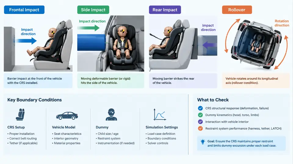
A child restraint system (CRS) is only as good as the load cases it is validated against. In explicit finite element (FE) crash simulation, the load case defines what the structure is subjected to, while the boundary conditions define how that load is transferred into and out of the model. Get either wrong and the simulation may converge cleanly while predicting a physically meaningless result. This chapter establishes the four primary load cases used in CRS development — frontal, side, rear impact, and rollover — and the boundary conditions that make each one reproducible.
Why the Load Case Set Matters
Regulatory and consumer-test protocols (ECE R44/R129, FMVSS 213, Euro NCAP, and C-NCAP) each prescribe specific impact velocities, pulse shapes, and fixture configurations. A CRS program typically runs a matrix of these cases because a design that performs well in frontal impact can fail badly in side impact, and vice versa. The simulation engineer's job is to translate each physical test into a defensible numerical model: a prescribed acceleration or velocity pulse applied to a sled or barrier, a defined occupant (Q-series or Hybrid III dummy), and a set of contact and constraint definitions that reproduce the test rig.
Frontal Impact
Frontal impact is the baseline case and the one most CRS structures are primarily tuned for. The standard approach is a sled test: the CRS and dummy are mounted on a sled that is accelerated or decelerated according to a prescribed pulse. In simulation, the sled is represented either as a rigid body with an imposed acceleration curve or as a prescribed velocity boundary condition on a rigid wall.
Key parameters for a typical frontal sled case:
- Impact velocity: 50 km/h (ECE R44 frontal), 56 km/h (FMVSS 213), or 64 km/h (Euro NCAP offset deformable barrier).
- Pulse shape: a deceleration-time history, often trapezoidal or a measured crash pulse, with peak deceleration around 20–30 g and duration 80–120 ms.
- Dummy: Q1.5, Q3, Q6, or Q10 depending on the CRS group; Hybrid III 3-year-old for FMVSS 213.
- Restraint: the CRS is attached via ISOFIX/latch anchors or a three-point belt, with the belt routed exactly as in the physical test.
In the FE model, the pulse is applied as a prescribed acceleration on the sled reference node, and the CRS anchorages are tied to that node through rigid or deformable connections. The critical outputs are head resultant acceleration (typically limited to 80 g over 3 ms), head excursion, chest deflection, and the neck injury criterion (Nij). A common modeling error is applying the pulse to the CRS base directly rather than to the sled, which bypasses the anchorage compliance and under-predicts excursion.
Side Impact
Side impact is the most demanding case for CRS lateral structure and head containment. Unlike frontal impact, the loading is highly asymmetric and the struck-side door intrudes into the occupant space. Two simulation approaches are common:
- Sled-based side impact: the CRS is mounted on a side-facing or lateral sled, and a moving barrier or door panel is driven into the CRS at a prescribed velocity (e.g., 25–30 km/h).
- Full-vehicle side impact: a deformable moving barrier strikes a stationary vehicle at 50 km/h (Euro NCAP side impact), and the CRS is modeled in its actual vehicle seat position.
Boundary conditions here include the door trim geometry, the seat cushion and backrest stiffness, and the CRS-to-vehicle attachment. The head is the primary injury target: lateral head acceleration and head-to-door contact force drive the result. A CRS with a deep side wing and energy-absorbing foam will show a different head trajectory than a low-profile seat, and the simulation must capture the contact sequence — head to wing, wing to door, door to barrier — in the correct order.
Rear Impact
Rear impact is often overlooked but is critical for rear-facing CRS, where the child's head and back are supported by the CRS shell. The load case is typically a rear sled pulse at lower velocity (e.g., 30–40 km/h) with a longer duration. The key concern is rebound: after the initial rearward acceleration, the CRS and dummy rebound forward, and the restraint must manage this without excessive head excursion.
In simulation, the rear pulse is applied in the opposite direction to the frontal case. The CRS shell must be modeled with correct bending stiffness, and the interface between the CRS and the vehicle seat back must be represented — a soft seat back allows more rotation, a stiff one transfers load directly. For rear-facing CRS, the critical output is the shell deflection and the head-to-shell contact pressure, since the shell is the primary load path.
Rollover
Rollover is a quasi-static or low-speed dynamic case that tests occupant retention and ejection prevention. Two simulation variants exist:
- Quasi-static rollover: the vehicle or sled is rotated about its longitudinal axis at a slow rate (e.g., 5–10 deg/s) to a prescribed angle, and the CRS must retain the dummy without ejection.
- Dynamic rollover: a prescribed angular velocity or a drop test is applied, and the CRS is evaluated for structural integrity and dummy retention.
Boundary conditions include the rotation axis, the ground contact (if the vehicle contacts the ground), and the belt/anchor behavior under combined loading. The main outputs are dummy displacement relative to the CRS, belt slip, and any shell cracking or anchor pull-out. Rollover is often run as a check case rather than a tuning case, but it can reveal retention failures that frontal and side cases miss.
Boundary Conditions Common to All Cases
Regardless of load case, several boundary conditions must be defined consistently:
| Boundary Condition | Typical Definition | Common Pitfall |
|---|---|---|
| Sled/barrier constraint | Rigid body with prescribed acceleration or velocity | Applying pulse to CRS base instead of sled |
| Anchorage | ISOFIX connectors or belt routing with correct stiffness | Rigid anchorage over-stiffens the system |
| Seat interface | Deformable foam or spring-damper representation | Rigid seat under-predicts rotation |
| Contact | CRS-to-dummy, CRS-to-door, CRS-to-seat | Missing contact pairs cause penetration |
| Gravity | 9.81 m/s² applied before impact | Omitted pre-load changes initial position |
The table above is a starting checklist, not a complete specification. Each load case will add its own constraints — for example, a side impact case needs a door intrusion curve, and a rollover case needs a rotation boundary. The engineer should document every boundary condition with its source (test protocol, measured data, or engineering assumption) so the model can be audited later.
Practical Guidance for Setting Up a Load Case
When building a new load case, start from the physical test protocol and work backward. Identify the pulse source (measured sled acceleration or prescribed barrier velocity), the fixture geometry, and the dummy model. Then define the boundary conditions in this order: (1) constrain the sled or barrier reference node, (2) attach the CRS through its real anchorages, (3) define the seat and door interfaces, (4) set up all contact pairs, and (5) apply gravity as a pre-load before the impact pulse. Run a short settling simulation to confirm the dummy and CRS are in equilibrium before the pulse starts; if the model drifts or oscillates during settling, the contact or constraint definitions need correction before any impact result is meaningful.
Finally, verify the pulse actually delivered to the model. Plot the acceleration of the sled reference node and compare it to the prescribed curve. If the delivered pulse is attenuated or phase-shifted, the boundary condition is too compliant or the time step is too large. This single check catches more setup errors than any other, and it should be part of every load case's acceptance criteria.