1. Introduction to Child Restraint System C
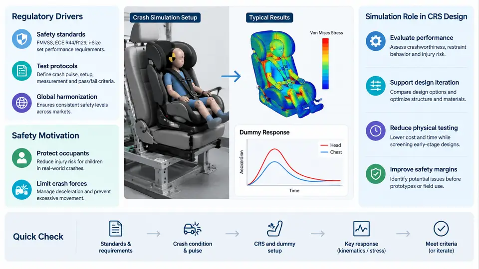
Every year, motor-vehicle crashes remain one of the leading causes of death and serious injury for children. A child occupant is not a scaled-down adult: the head is proportionally larger and heavier, the neck is weaker, the rib cage is more compliant, and the pelvis is not yet fully ossified. These anatomical differences mean that restraint loads must be distributed over different body regions and at different magnitudes than for adults. A Child Restraint System (CRS) — an infant carrier, a convertible seat, a booster, or an integrated child seat — exists to manage those loads. Crash simulation is the engineering discipline that lets designers predict, before any hardware exists, whether a given CRS will manage them well enough.
Why regulation forces simulation into the design loop
The regulatory landscape is the primary driver. In the United States, FMVSS 213 defines frontal sled tests for CRS, with the Hybrid III 3-year-old and 6-year-old ATDs (Anthropomorphic Test Devices) and, more recently, the Q3s side-impact ATD under FMVSS 213a. In Europe, UN Regulation No. 129 (the "i-Size" regulation) introduced the Q-series ATDs, mandatory side-impact assessment, and a classification by child height rather than weight. UN R44 remains in force for older approvals. China's GB 27887 aligns closely with R44/R129 practice, and consumer programmes such as Euro NCAP and C-NCAP add their own, often stricter, protocols.
What matters for the simulation engineer is not the list of regulations but their structure. Each protocol specifies a sled pulse (a deceleration–time history), a seat fixture geometry, a belt routing and anchorage layout, an ATD, and a set of injury criteria with pass/fail thresholds. The most common criteria are:
- HIC (Head Injury Criterion), computed from the resultant head acceleration over the most severe 15 ms window;
- Head resultant acceleration, limited to 80 g for a 3 ms clip in many protocols;
- Neck injury — tension, compression, and bending moment, often combined into Nij;
- Chest deflection and the 3 ms chest acceleration clip;
- Head excursion — the forward and lateral displacement of the head reference point, which is what keeps a child from striking the vehicle interior.
Because a physical sled test costs thousands of dollars, consumes a seat, and yields data only after the fact, simulation is used to explore the design space first. A typical programme runs dozens or hundreds of virtual configurations for every one physical test.
What a CRS crash simulation actually contains
A production-grade model is an explicit-dynamics finite element (or multi-body + FE hybrid) assembly. The essential subsystems are:
| Subsystem | Typical representation | Key modelling concern |
|---|---|---|
| ATD (Q3, Q6, Hybrid III 3yo) | Validated FE dummy model | Mesh quality, joint stiffness, certification corridors |
| CRS shell and foam | Shell elements + crushable foam | Strain-rate dependence, foam densification |
| Harness and vehicle belt | 1D seatbelt elements with sliprings | Friction, retractor and pretensioner behaviour |
| ISOFIX / LATCH connectors | Rigid or deformable connectors | Anchor compliance, latch release loads |
| Vehicle seat and interior | Simplified FE or rigid body | Seat cushion stiffness, armrest and door trim contact |
| Sled pulse | Prescribed acceleration or initial velocity | Pulse fidelity, filtering, integration drift |
The simulation is driven by a prescribed deceleration pulse applied to the sled, or by an initial velocity plus gravity. Contact is defined between the ATD and the CRS, the CRS and the vehicle seat, and the ATD and any interior surface it may reach. The solver advances the solution with an explicit time step limited by the smallest element and the local wave speed, so a 120 ms event typically requires hundreds of thousands of cycles.
The simulation workflow in practice
Consider a concrete example: a convertible CRS evaluated in a frontal 50 km/h sled test with a Q3 ATD, forward-facing, using the vehicle's three-point belt routed through the CRS belt guides. The engineer's sequence is roughly:
- Build the model. Import the CRS CAD, mid-surface it, mesh with a target element size of 5–8 mm on the shell and 10 mm on foam. Assign material cards: polypropylene shell with a piecewise-linear plasticity curve, EPS foam with a stress–strain curve that includes the plateau and densification region.
- Position the ATD. Seat the Q3 per the regulation's installation procedure — H-point location, torso angle, and limb positions are all specified. A 2–5 mm initial penetration into the seat cushion is normal and is resolved in the first few milliseconds.
- Route the belt. Define the belt path through the guides, set the retractor locking time, and apply a pretension of 2–4 kN if the vehicle has a pretensioner. Friction coefficients between belt and CRS are typically 0.2–0.3.
- Apply the pulse. Load the sled acceleration curve, filter it per SAE J211 CFC 60, and verify that the integrated velocity returns to zero at the end of the event.
- Run and inspect. Check the energy balance, the hourglass energy (should stay below 5% of internal energy), and the added-mass ratio. Then extract the ATD accelerations and compute HIC, head excursion, and chest deflection.
Typical failure symptoms and their causes: if the model terminates early with negative volume errors, the foam or shell elements are over-compressed and need a better material card or a smaller time step. If hourglass energy climbs above 10%, the shell mesh is too coarse or the element formulation is wrong. If the ATD's head excursion is far below the physical test, the belt is probably too stiff or the friction is too high. If HIC is unrealistically high, check the contact stiffness between the head and the CRS — an over-stiff contact is a common modelling artefact.
Where simulation fits in the design cycle
Simulation is not a replacement for physical testing; it is a filter that makes physical testing affordable and informative. In the concept phase, coarse models compare architectures — rear-facing versus forward-facing, ISOFIX versus belt-routed. In the detailed design phase, high-fidelity models optimise foam thickness, shell ribbing, and belt guide position. In the validation phase, simulation is correlated against sled tests, and the correlation itself becomes the evidence that the model is trustworthy for the next programme.
What this course will build
The remaining chapters move from this overview into the mechanics of building, running, and trusting a CRS crash model. You will work with explicit solver setup, material calibration for foam and polymers, belt and contact definition, ATD positioning, pulse preparation, and correlation against sled data. The goal is not merely to run a deck that terminates without error, but to produce a model whose predictions you can defend in a design review — and whose numbers you would be willing to bet a physical test on.