4. Center airbag system architecture
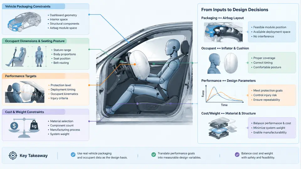
A center airbag is not a single part but a small system whose behavior is decided long before the first simulation run. The architecture defines how the gas generator, the cushion, the tethers, and the mounting interfaces interact, and it determines whether the restraint can be packaged, deployed, and validated within the vehicle interior. This section describes the physical architecture of a center airbag system, the function of each subsystem, and the interface parameters that must be fixed before CAE work begins.
System decomposition
A production center airbag system can be decomposed into five functional groups:
- Module assembly — the housing, cover, and structural bracket that retain the folded cushion and the inflator, and that transfer deployment reaction loads into the seat or console structure.
- Inflator — the gas generator, either pyrotechnic, hybrid, or stored-gas, that supplies the mass flow required to fill the cushion within the target time window.
- Cushion — the woven fabric envelope, including the panel layout, seams, and venting features that control internal pressure and occupant interaction.
- Tether system — internal or external straps that limit cushion excursion, shape the deployed geometry, and tune the effective restraint stiffness.
- Mounting interfaces — the mechanical and electrical connections between the module and the vehicle: bracket bolt pattern, seat frame attachment, wiring harness, and connector orientation.
These groups are coupled. A change in inflator output changes cushion pressure, which changes tether loading, which changes the reaction force transmitted through the mounting bracket. Architecture work therefore means fixing the interfaces between these groups, not optimizing them independently.
Inflator selection and output characteristics
The inflator is specified primarily by its gas output curve: mass flow rate versus time, and total gas mass at a reference temperature. For a typical seat-mounted center airbag, the fill target is reached in roughly 20–35 ms after the trigger signal. A representative hybrid inflator for this application might deliver approximately 1.2–1.8 mol of gas with a peak mass flow near 60–90 g/s, but these values must always be treated as example figures until confirmed against the supplier datasheet.
Two inflator parameters dominate the architecture:
- Exit port geometry — determines the jet direction and the local loading on the cushion inlet. A poorly oriented port can scorch the fabric or create a pressure spike near the inlet seam.
- Temperature sensitivity — gas output varies with ambient temperature. The architecture must remain valid across the validation range, typically −35 °C to +85 °C, with the hot and cold cases producing different fill times and peak pressures.
Cushion construction and venting
The cushion is defined by its panel layout, seam pattern, fabric permeability, and vent holes. For a center airbag, the cushion typically deploys between the two front occupants, so its shape is asymmetric: it must reach across the gap while remaining anchored at the inboard side of the seat or console.
Key cushion parameters include:
| Parameter | Typical example value | Architectural effect |
|---|---|---|
| Fabric permeability | 0.5–3.0 L/dm²/min at 500 Pa | Controls pressure decay after peak; higher permeability reduces rebound |
| Vent hole area | 2 × 25 mm diameter | Primary pressure relief path; affects occupant deceleration |
| Seam strength | ≥ 3.5 kN per 50 mm seam | Must exceed peak internal pressure loading with margin |
| Panel count | 2–4 panels | Determines 3D shape and fold pattern complexity |
Venting is the main tuning lever for occupant loading. A larger vent area lowers peak pressure and reduces the risk of high chest deflection, but it also shortens the effective restraint duration. The architecture must therefore balance venting against tether restraint, not treat them as independent adjustments.
Tether function and routing
Tethers serve three purposes: limiting cushion excursion, shaping the deployed envelope, and transferring load between cushion panels. In a center airbag, a common configuration uses an internal tether that connects the outboard panel to the inboard panel, preventing the cushion from over-expanding toward the opposite occupant.
Tether parameters that must be fixed at the architecture stage:
- Anchor points — the seam locations where the tether is sewn. These define the effective tether length and the deployed geometry.
- Length — a shorter tether produces a flatter, more constrained cushion; a longer tether allows more excursion.
- Material and width — typically a woven nylon strap, 25–50 mm wide, with a breaking strength well above the expected deployment load.
- Routing path — whether the tether runs internally through the cushion volume or externally along the surface. Internal routing protects the tether but complicates folding.
Because tether length directly changes the deployed shape, it is one of the first parameters to sweep in simulation. A ±10 mm change in tether length can shift the cushion contact surface by a comparable amount, which is significant when the available gap between occupants is limited.
Mounting interfaces
The mounting interface is where the module meets the vehicle. For a seat-mounted center airbag, the module bracket typically attaches to the seat frame with two or three M8 bolts, and the inflator connector is routed along the seat harness. The interface must satisfy three requirements:
- Structural — the bracket must withstand the deployment reaction force without permanent deformation. A representative peak reaction force for a center airbag is in the range of 2–5 kN, depending on inflator output and cushion pressure.
- Positional — the module orientation relative to the seat determines the deployment direction. A few degrees of misalignment can redirect the cushion toward the occupant or into the seat structure.
- Electrical — the connector must remain seated under vibration and must not be loaded by the deploying cushion or tether.
Architecture integration flow
The figure below shows how the five subsystem groups connect and which parameters flow between them. It is a structural and interface diagram, not a deployment sequence: the arrows represent parameter dependencies that must be resolved during architecture definition.
Interface parameters to freeze before simulation
The following parameters should be fixed at the architecture stage, because changing them later invalidates the mesh, the fold model, and the contact definitions:
| Interface | Parameter | Example value |
|---|---|---|
| Inflator → Cushion | Inlet port diameter | 18 mm |
| Inflator → Module | Retention flange bolt torque | 8 N·m |
| Cushion → Tether | Anchor seam offset from inlet | 120 mm |
| Tether | Effective length | 280 mm |
| Module → Seat frame | Bolt pattern | 2 × M8, 80 mm spacing |
| Module → Harness | Connector orientation | Downward, 30° from vertical |
Once these values are frozen, the CAE model can be built with confidence that the architecture is internally consistent. Any later change should be treated as an architecture revision, not a simulation tweak, and should trigger a review of the coupled interfaces described above.
Practical verification of the architecture
Before committing to a full simulation campaign, a static packaging check and a component-level deployment test can catch most interface errors. A practical sequence is:
- Verify the folded cushion fits within the module housing with the specified compression ratio, typically 1.5–2.5 for a center airbag.
- Confirm the inflator exit ports align with the cushion inlet without obstruction from the fold or the tether.
- Check that the tether anchor seams do not intersect the inflator retention flange.
- Measure the bracket bolt hole positions against the seat frame drawing, allowing for weld distortion of ±1.5 mm.
- Route the harness and confirm the connector cannot be loaded by the deploying cushion.
If any of these checks fail, the architecture must be revised before mesh generation. Correcting an interface after the model is built typically costs several times more effort than resolving it at the architecture stage, because the fold pattern, the contact definitions, and the boundary conditions all depend on the frozen interface set.
The architecture described here provides the input for the next stage of work: building the folded cushion model and defining the deployment boundary conditions in the simulation environment.