1. Airbag inflator fundamentals
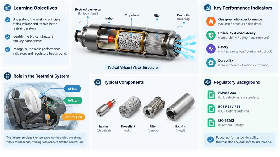
An airbag inflator is a controlled gas generator. Its job is deceptively simple to state: within tens of milliseconds of a valid crash signal, it must deliver a specified mass of gas at a specified temperature and pressure into a cushion, so that the cushion is fully deployed and properly vented before the occupant's torso arrives. Everything difficult about inflator engineering follows from that sentence — the timing, the gas thermodynamics, the structural containment, and the safety of a device that stores or creates energy in a form that must remain inert for the entire service life of the vehicle.
This chapter establishes the vocabulary and the physical picture that the rest of the course builds on: where the inflator sits in the restraint system, how the three main inflator families generate gas, and which metrics are used to characterize and compare them.
1.1 The inflator's role in the occupant restraint system
A frontal restraint system is a chain of sensing, decision, actuation, and energy absorption. The inflator is the actuation element, but it never acts alone. A typical chain is:
- Crash sensors — accelerometers in the airbag ECU (and often satellite or pressure sensors in the doors or B-pillars) produce acceleration or pressure signals.
- Restraint ECU — applies a crash algorithm, performs safing logic, and decides whether and when to fire.
- Inflator — receives the fire command and converts stored chemical or pneumatic energy into gas.
- Cushion and module hardware — the cushion, tethers, vents, and module housing shape the gas into a usable restraint surface.
- Occupant and seat belt — the belt carries most of the restraint load; the airbag distributes the remaining load over a larger area and limits head and chest excursion.
Two consequences of this chain matter for inflator characterization. First, the inflator is a time-critical device: the ECU's fire decision typically occurs 10–30 ms after impact, and the cushion must be pressurized before the occupant moves into the deployment zone. Second, the inflator is a tuned device: its output must match the cushion volume, vent area, and occupant position. An inflator that is "too strong" is not safer — it raises internal cushion pressure and can increase injury risk for out-of-position occupants.
1.2 Inflator types
Three families dominate production vehicles. They differ in where the gas comes from and therefore in temperature, composition, packaging, and cost.
| Type | Gas source | Typical gas temperature | Typical use |
|---|---|---|---|
| Pyrotechnic | Solid propellant combustion | High (often >1000 K at the combustion zone) | Driver and passenger frontal modules |
| Hybrid | Propellant heats stored inert gas | Moderate (several hundred K) | Passenger modules, side airbags |
| Stored gas | Compressed gas released by a valve | Near ambient (cold gas) | Side and curtain airbags, some pedestrian protection |
Pyrotechnic inflators burn a solid propellant — historically sodium azide, now more commonly guanidine nitrate or similar formulations — in a combustion chamber. The gas passes through a filter and cooler before entering the cushion. They are compact and inexpensive, but the gas is hot and contains particulates that the filter must capture.
Hybrid inflators combine a small pyrotechnic charge with a stored inert gas, usually argon or helium at 20–40 MPa. The burning propellant heats the stored gas, raising its pressure and therefore the delivered mass flow. The result is a cooler, cleaner gas than a pure pyrotechnic inflator, at the cost of a heavier pressure vessel.
Stored-gas inflators hold compressed gas behind a burst disc or a fast-acting valve. They are the coldest option and are well suited to side airbags, where the cushion is small and the occupant is close. Their main drawback is the mass and volume of the pressure vessel and the slow leak-down over service life.
1.3 Key performance metrics
Inflator performance is described by a small set of measurable quantities. These are the quantities that appear in a datasheet, in a tank test, and in a simulation input deck.
- Gas yield (mass of gas) — total mass of gas delivered to the cushion, in grams or moles. Determines the cushion's peak pressure for a given volume.
- Mass flow rate — the time history of gas delivery, ṁ(t), in g/ms or kg/s. This is the single most important curve for simulation.
- Time to first gas (TTFG) — delay between the fire command and the first measurable gas output. Typically 1–5 ms.
- Time to 50% mass (t₅₀) — a compact scalar summarizing how fast the inflator delivers its gas.
- Gas temperature — affects cushion pressure and the thermal load on the cushion fabric.
- Peak pressure and burst strength — the inflator body must contain the combustion or stored-gas pressure with margin.
- Particulate and residue mass — matters for filter design and for occupant exposure.
- Service-life stability — the inflator must meet its performance after years of thermal cycling and vibration.
These metrics are not independent. Increasing gas yield usually increases peak pressure and mass; increasing mass flow rate usually increases gas temperature. Characterization is the process of measuring these quantities and understanding how they trade against each other.
1.4 How the metrics are measured: the tank test
The standard characterization method is the tank test (also called a closed-vessel or pressure-vessel test). The inflator is fired into a sealed tank of known volume, and the tank pressure is recorded versus time. From the pressure trace, the delivered gas mass and mass flow rate are derived using the ideal-gas relation:
m(t) = (P(t) - P0) * V / (R * T_tank)

where:
  P(t)   = measured tank pressure at time t   [Pa]
  P0     = initial tank pressure              [Pa]
  V      = tank volume                        [m^3]
  R      = specific gas constant of the gas   [J/(kg*K)]
  T_tank = gas temperature in the tank        [K]

mass flow rate:  mdot(t) = dm/dt  [kg/s]
In practice, T_tank is not constant — the gas entering the tank is hot and then cools — so the simple relation is corrected with a measured or modeled temperature history, or the tank is calibrated against a reference inflator. This is why tank-test results are reported together with the tank volume, the initial pressure, and the gas constant used.
1.5 From inflator to cushion: the pressure balance
The inflator does not act in isolation. The cushion pressure at any instant is set by the balance between gas inflow and outflow through the vents and fabric porosity:
dP_cushion/dt = (gamma * R * T / V_cushion) * mdot_in
                - (gamma * P_cushion / V_cushion) * dV_cushion/dt
                - vent and porosity losses
This is the equation that a simulation must reproduce. It shows why the inflator's mass flow curve ṁ(t) is the key input: it drives the cushion pressure, which in turn drives the force on the occupant. The rest of this course builds the tools to measure ṁ(t), model it, and validate the model against tank and sled tests.
1.6 What characterization must deliver
By the end of a characterization campaign, an engineer should be able to answer four questions with data:
- How much gas? Total delivered mass, with tolerance, at reference and at temperature extremes.
- How fast? The ṁ(t) curve, or at minimum TTFG and t₅₀, at reference and at extremes.
- How hot and how clean? Gas temperature history and particulate mass, since both affect cushion durability and occupant exposure.
- How repeatable? Shot-to-shot scatter and unit-to-unit scatter, which set the safety margin in the restraint design.
These four answers become the input to the simulation models developed later in this course. The next chapter examines the thermodynamic and chemical processes inside the inflator that produce the ṁ(t) curve in the first place.