1. Introduction to vehicle rollover and roo
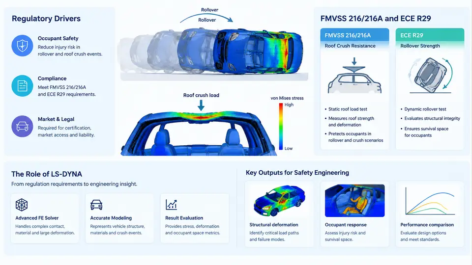
Vehicle rollover is one of the most consequential crash modes in occupant safety engineering. Although rollovers account for a relatively small share of all police-reported crashes, they are disproportionately represented in fatal and serious-injury statistics, largely because the occupant compartment can be loaded directly when the roof structure contacts the ground. Roof crush simulation exists to answer a deceptively simple question: when a vehicle lands on its roof, does the occupant survival space remain intact long enough for the restraint system to do its job? This chapter establishes the regulatory landscape that forces that question, the two dominant test standards that formalize it, and the role LS-DYNA plays in answering it during vehicle development.
Why Rollover and Roof Crush Matter
Rollover differs fundamentally from frontal or side impact. In a frontal crash, the primary load path runs through the front structure, and the occupant is restrained by belts and airbags against a relatively predictable deceleration pulse. In a rollover, the vehicle may experience multiple ground contacts, the loading direction changes continuously, and the roof and pillars become the primary structural barrier between the occupant and the ground. If the roof crushes inward beyond a critical limit, the occupant's head and neck can be exposed to direct contact with the roof rail or ground surface, and the effective survival space shrinks.
Two physical quantities dominate the engineering discussion. The first is roof crush resistance, the force the roof structure can sustain as it deforms under a quasi-static or dynamic load. The second is occupant survival space, the residual volume around the seated occupant after deformation. Regulatory tests are essentially standardized ways of measuring the first quantity and inferring the second. Simulation must reproduce both the structural force–displacement response and the resulting occupant kinematics.
Regulatory Drivers: FMVSS 216 and 216A
In the United States, Federal Motor Vehicle Safety Standard (FMVSS) 216, "Roof Crush Resistance," is the governing regulation. The original FMVSS 216, effective from the 1970s, applied a quasi-static load to one side of the roof through a rigid rectangular platen. The platen was oriented at a fixed pitch and roll angle, and the vehicle had to withstand a specified force without the roof deforming beyond a limit. The original test was widely criticized because it applied only a single-side load and used a force level that many vehicles could pass with modest structural reinforcement.
FMVSS 216A, introduced in 2009 and phased in through 2012, substantially strengthened the requirement. The key changes are:
- Both sides are tested. The platen is applied to the driver side and then to the passenger side, so a vehicle cannot pass by reinforcing only one side.
- Higher force requirement. The roof must withstand a multiple of the vehicle's unloaded weight, up to a specified cap, rather than a fixed force.
- Platen travel limit. The platen may not travel more than a specified distance (typically 127 mm) before the required force is reached.
- Head injury criterion consideration. The standard also addresses the potential for head contact with the roof structure.
The practical consequence is that 216A forces engineers to design roof rails, B-pillars, and roof bows as a coordinated load path rather than as isolated components. A typical passenger car must now sustain a roof force on the order of two to three times its own weight, depending on vehicle class and the weight cap.
ECE R29 and the European Perspective
In Europe, the equivalent regulation is ECE R29, "Protection of the Occupants of the Cab of a Commercial Vehicle." ECE R29 is historically associated with commercial vehicle cabs, but its principles—roof strength, survival space, and occupant protection under roof loading—parallel FMVSS 216. ECE R29 defines a survival space within the cab and requires that after the application of a specified roof load, no part of the survival space is intruded upon. The test is quasi-static and uses a rigid platen applied to the roof.
The two standards differ in detail: FMVSS 216A is expressed primarily as a force requirement with a travel limit, while ECE R29 is expressed as a survival-space requirement after a defined load. For a global vehicle program, the design must satisfy both, which usually means the more demanding of the two governs the roof structure. In practice, engineers build a single roof architecture and verify it against both load cases.
The Role of LS-DYNA in Occupant Safety Engineering
LS-DYNA is an explicit finite element solver widely used for crashworthiness simulation. Its explicit time integration scheme is well suited to the highly nonlinear, contact-dominated, large-deformation problems that roof crush represents. In a roof crush simulation, the model typically includes:
- The body-in-white (BIW) with roof rails, roof bows, A/B/C pillars, and the roof panel, meshed with shell elements and assigned elastic–plastic material models with strain-rate dependence.
- The rigid platen representing the regulatory loading device, modeled as a rigid body with a prescribed motion or force.
- Contact definitions between the platen and the roof structure, and self-contact within the deforming structure.
- Boundary conditions that constrain the vehicle body at the suspension or body mounts to represent the test fixture.
The simulation is driven either by prescribing the platen displacement and reading the resulting reaction force, or by prescribing the force and reading the displacement. The output of interest is the force–displacement curve, from which the peak force, the energy absorbed, and the travel at the required force level are extracted. These quantities are compared directly against the regulatory thresholds.
From Regulation to Simulation: A Practical Example
Consider a mid-size SUV with an unloaded weight of 2,100 kg. Under FMVSS 216A, the required roof force is a multiple of the vehicle weight, capped at a specified value. Suppose the applicable requirement is 2.5 times the vehicle weight, giving a target force of approximately 51.5 kN. The simulation must demonstrate that the roof structure reaches this force before the platen travels 127 mm.
A typical LS-DYNA deck for this problem would include the following key cards. The platen is defined as a rigid body with a prescribed velocity or displacement:
*MAT_RIGID
$#   mid        ro         e        pr        n    couple         m
         1    7.85e-9   2.10e5       0.3        0        0        0
$#   cmo      con1      con2
         1         0         0

*BOUNDARY_PRESCRIBED_MOTION_RIGID
$#   pid       dof       vad      lcid        sf       vid
         1         3         0       100       1.0         0

*DEFINE_CURVE
$#  lcid      sidr       sfa       sfo       off       oft
       100         0       1.0       1.0       0.0       0.0
$#                abscissa                    ordinate
                 0.000000                  0.000000
                 0.050000                 -5.000000
                 0.100000                -10.000000
Here the platen moves downward at a prescribed velocity, and the reaction force is extracted from the contact interface. The roof structure is modeled with shell elements using a strain-rate-dependent plasticity model such as *MAT_PIECEWISE_LINEAR_PLASTICITY (MAT 24) or *MAT_PLASTIC_KINEMATIC (MAT 3). Spot welds and adhesive bonds between the roof panel and the roof rails are represented with *CONSTRAINED_SPOTWELD or cohesive elements, since these joints often govern the failure sequence.
After the run, the engineer plots the reaction force versus platen displacement. The pass criteria are straightforward: the curve must reach the required force before 127 mm of travel, and the deformed shape must not intrude into the occupant survival space. If the peak force is reached too late, the usual remedies are to increase the gauge of the roof rail, add a roof bow, or improve the B-pillar-to-roof joint. If the structure fails prematurely at a weld, the weld layout or the local material grade is adjusted.
What This Course Covers
This course builds from the regulatory foundation established here into the full simulation workflow: geometry preparation and meshing of the BIW, material model selection for high-strength steels and aluminum, contact definition, boundary conditions that match the test fixture, solver settings for stable explicit integration, and post-processing that extracts the force–displacement curve and survival-space check. Later chapters also address dynamic rollover simulation, occupant kinematics, and validation against physical test data. The goal is to equip you to build, run, and defend a roof crush model that a regulator or a vehicle program would accept.
The essential takeaway from this chapter is that roof crush simulation is not an academic exercise. It is a regulatory compliance activity with defined pass/fail criteria, and LS-DYNA is the tool of record for most global vehicle programs. Understanding the standards first—FMVSS 216A's force-and-travel criterion and ECE R29's survival-space criterion—is what makes the simulation results meaningful rather than merely numerical.