1. Course overview
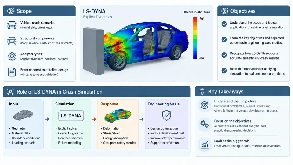
Vehicle crash simulation is one of the most demanding applications of explicit finite element analysis. A full frontal impact model of a modern passenger car routinely contains 8–15 million elements, hundreds of material models, multiple contact interfaces, and a solution that advances in microseconds. LS-DYNA, developed originally at Lawrence Livermore National Laboratory and now maintained by Ansys, has become the de facto industry standard for this class of problem. This course is built around engineering case studies rather than software feature tours: each chapter takes a realistic crashworthiness task — a frontal offset barrier test, a side pole impact, a seat-belt anchorage pull, a battery-pack intrusion study — and works through the modeling decisions, solver settings, and result interpretation that determine whether the simulation is trustworthy.
What This Course Covers
The scope spans the complete simulation workflow as it is actually practiced in OEM and Tier-1 engineering groups:
- Model build and assembly. CAD cleanup and meshing strategy for thin-walled stamped parts, spot-weld and adhesive representation, material card selection for steels, aluminum, plastics, and foams, and the construction of a runnable keyword deck.
- Load case definition. Barrier geometry and initial velocity per regulatory and consumer protocols (FMVSS 208, ECE R94/R95, Euro NCAP, C-NCAP), occupant and restraint modeling, and the boundary conditions that keep the model stable.
- Solver configuration. Time-step control, mass scaling, contact algorithms (
*CONTACT_AUTOMATIC_SINGLE_SURFACE,*CONTACT_AUTOMATIC_SURFACE_TO_SURFACE), hourglass control, and the termination and output settings that make a run reproducible. - Result validation. Correlation against physical sled and full-vehicle test data, energy balance checks, intrusion and acceleration pulse comparison, and the judgment calls behind accepting or rejecting a model.
The course assumes working familiarity with finite element fundamentals and basic LS-DYNA keyword syntax. It does not assume prior crash-specific experience; the case studies introduce the domain conventions as they become relevant.
Learning Objectives
By the end of the course, a participant should be able to:
- Translate a crash test protocol into a defensible simulation load case, including barrier type, impact speed, and instrumentation points.
- Build and debug a vehicle crash model that runs to termination without numerical instability, and explain the root cause when it does not.
- Select material models and parameters appropriate to the strain rates and failure modes present in a given impact scenario.
- Read an energy balance, a contact interface force plot, and a section-force history, and use them to diagnose modeling errors rather than merely report numbers.
- Correlate simulation output against test measurements and quantify the remaining discrepancy in engineering terms.
Why LS-DYNA for Crash Simulation
LS-DYNA's suitability for crash work rests on several technical properties that are difficult to replicate in a general-purpose implicit solver. The explicit central-difference time integration scheme avoids assembling and factorizing a global stiffness matrix, so cost scales roughly linearly with element count and the method tolerates the severe nonlinearity, contact, and element distortion that characterize a crush event. The solver's contact library handles self-contact of folded sheet metal, which is the dominant load path in a front-end structure. Its material library includes rate-dependent plasticity (Johnson-Cook, Cowper-Symonds), damage and failure models (GISSMO, MAT_ADD_EROSION), and dedicated formulations for foams, honeycombs, and composites. Finally, the keyword-deck format is text-based and diffable, which makes model version control and automated regression testing practical at the scale of a vehicle program.
The Simulation Workflow at a Glance
The diagram below shows how the major activities in a crash simulation project relate to one another, and where the feedback loops that consume most engineering time actually sit. Note that correlation is not a terminal step — it feeds back into material calibration and model build, often more than once.
How the Case Studies Are Structured
Each chapter presents a self-contained engineering problem with concrete inputs. Where a parameter is given, it is either taken from a published protocol or explicitly labeled as an illustrative assumption. For example, a frontal rigid-barrier case will state the impact velocity (56 km/h for the ECE R94 offset deformable barrier, or 35 mph for FMVSS 208 full frontal), the barrier geometry, and the vehicle mass, then show the corresponding *INITIAL_VELOCITY and *RIGIDWALL definitions. Where a result is shown, it is presented as an expected trend or a representative output, not as a measured test value unless the source is identified.
A recurring theme is the distinction between a simulation that runs and a simulation that is correct. A model can terminate normally while producing an energy balance that drifts, a contact interface that penetrates, or an acceleration pulse that is numerically smooth but physically wrong. The case studies deliberately include these failure modes — negative volume errors in solid elements, excessive hourglass energy, contact instability from inverted normals — and walk through the diagnostic sequence: check the d3hsp file for the first warning, inspect the energy summary in glstat, locate the offending part in matsum, and correct the underlying modeling cause rather than masking it with a solver switch.
Prerequisites and Tooling
Participants should have access to LS-DYNA (R11 or later is assumed for keyword examples), a pre-processor capable of writing LS-DYNA keyword decks (LS-PrePost, ANSA, or HyperMesh), and a post-processor for time-history and contour review. A Linux or Windows workstation with at least 16 cores is recommended for the full-vehicle cases; the smaller component cases in the early chapters run comfortably on 4–8 cores. All keyword snippets in this course are written for the standard LS-DYNA input format and can be pasted directly into a deck, with the understanding that node, element, and part IDs must be adapted to the model at hand.
The chapters that follow move from component-level validation toward full-vehicle correlation, building the modeling vocabulary incrementally. The first case study examines a simple axial crush tube, which isolates the material and contact behavior that later reappear at vehicle scale.