4. Material modeling for steering column co
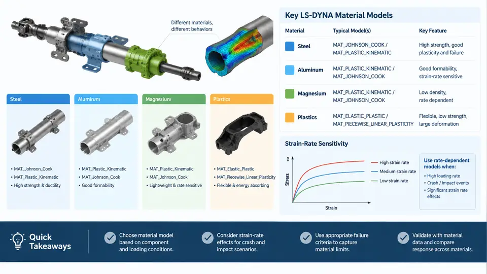
The steering column is a multi-material assembly. The jacket tube, upper and lower shafts, mounting brackets, and shear capsules are typically steel; the energy-absorbing strap or sliding sleeve may be aluminum; some bracket castings and instrument-panel support nodes use magnesium alloys; and the telescoping interface, bearing cages, and trim covers rely on engineering plastics. A frontal impact simulation is only as credible as the constitutive models assigned to these parts, because the collapse stroke, the peak force at the steering wheel, and the separation of the shear capsules are all governed by plastic flow, strain-rate hardening, and failure strain rather than by geometry alone.
Steel: Piecewise Plasticity with Rate Sensitivity
For the column jacket and shaft, the standard LS-DYNA choice is *MAT_PIECEWISE_LINEAR_PLASTICITY (MAT_024). It accepts a true stress–plastic strain table (LCSS) and, optionally, a strain-rate-dependent yield table (LCSR). A typical mild steel for a jacket tube might use the following card excerpt:
*MAT_PIECEWISE_LINEAR_PLASTICITY
$#     mid        ro         e        pr      sigy      etan      fail       tdel
         1  7.85e-09    210000       0.3       210       1.2       0.0       0.0
$#    lcss      lcsr        vp
         1         1       0.0
*DEFINE_CURVE
$#    lcid      sidr       sfa       sfo      offa      offo
         1         0       1.0       1.0       0.0       0.0
$#                 abscissa                ordinate
                   0.000                 210.0
                   0.020                 310.0
                   0.080                 420.0
                   0.150                 480.0
*DEFINE_CURVE
$#    lcid      sidr       sfa       sfo      offa      offo
         1         0       1.0       1.0       0.0       0.0
$#                 abscissa                ordinate
                   0.001                 1.00
                 100.000                 1.35
                 1000.00                 1.55
Here RO is in t/mm³, E in MPa, and the rate curve multiplies the static yield surface. The abscissa of LCSR is effective plastic strain rate in s⁻¹. For a column that collapses at 3–8 m/s, local strain rates in the shear capsule and strap reach 10²–10³ s⁻¹, so ignoring LCSR under-predicts the collapse force by 20–40 % and produces an unrealistically soft steering-wheel force–displacement curve.
Aluminum and Magnesium: Rate-Insensitive vs. Rate-Sensitive
Aluminum energy-absorbing straps are often modeled with MAT_024 as well, but with a much lower failure strain (0.08–0.15) and a weaker rate dependence. Magnesium die-cast brackets, by contrast, are brittle and rate-sensitive; *MAT_CRASHABLE or *MAT_PLASTICITY_WITH_DAMAGE (MAT_081) is more appropriate because it couples plasticity with a damage parameter that drives element deletion. A practical magnesium bracket card uses FAIL around 0.03–0.06 and a rate curve that raises flow stress by roughly 1.2× at 100 s⁻¹.
Plastics: Elastic–Plastic with Failure
Bearing cages and trim covers are usually modeled with *MAT_PLASTIC_KINEMATIC (MAT_003) or *MAT_PIECEWISE_LINEAR_PLASTICITY with a low yield stress (20–60 MPa) and a failure strain of 0.05–0.20. Because these parts are non-structural, they are often assigned a coarser mesh and a higher FAIL to avoid spurious element deletion that would otherwise remove mass from the model.
FAIL to a large value (e.g., 1.0) and rely on contact rather than erosion to represent its presence.Choosing the Right Model: A Decision View
The figure below maps the four material families to their LS-DYNA constitutive models and the dominant rate/failure parameters that control the steering column collapse response.
Calibration and Verification Workflow
Material cards should not be copied from a handbook without verification. A practical workflow for a steering column project is:
- Coupon-level check. Build a single-element or small tensile specimen model, apply a prescribed velocity, and compare the simulated force–displacement curve against the target. For steel, confirm that the rate multiplier at 100 s⁻¹ matches the intended 1.35×.
- Component-level check. Model the jacket tube and strap alone, impose a 6 m/s axial stroke, and extract the collapse force. A well-calibrated steel/aluminum pair should produce a plateau within ±10 % of the target energy-absorption force.
- Full-column check. Assemble the complete column with the steering wheel and verify that the peak force at the wheel hub stays below the injury-reference threshold and that the shear capsules release at the designed load.
LCSR is over-amplifying the yield surface. If the force is too low, verify that FAIL is not deleting elements prematurely, which removes load-carrying area and softens the response.Common Pitfalls
| Symptom | Likely Cause | Corrective Action |
|---|---|---|
| Collapse force 30 % low | LCSR omitted or flat | Add rate curve with 1.35× at 100 s⁻¹ |
| Sudden force drop | FAIL too low on aluminum strap | Raise FAIL to 0.12–0.15 or use damage-based model |
| Magnesium bracket shatters early | MAT_024 without damage | Switch to MAT_081 with FAIL 0.04 |
| Plastic cover disappears | FAIL set to 0.05 | Set FAIL = 1.0 for non-structural parts |
In summary, the steel and aluminum energy-absorbing members dominate the collapse force and must carry rate-dependent plasticity; magnesium brackets require damage-coupled models to capture brittle fracture; and plastics should be modeled with high failure strain to preserve mass and contact. Verifying each family at coupon, component, and full-column levels ensures that the material data, not numerical artifacts, controls the simulated crash response.