1. Steering column impact safety fundamenta
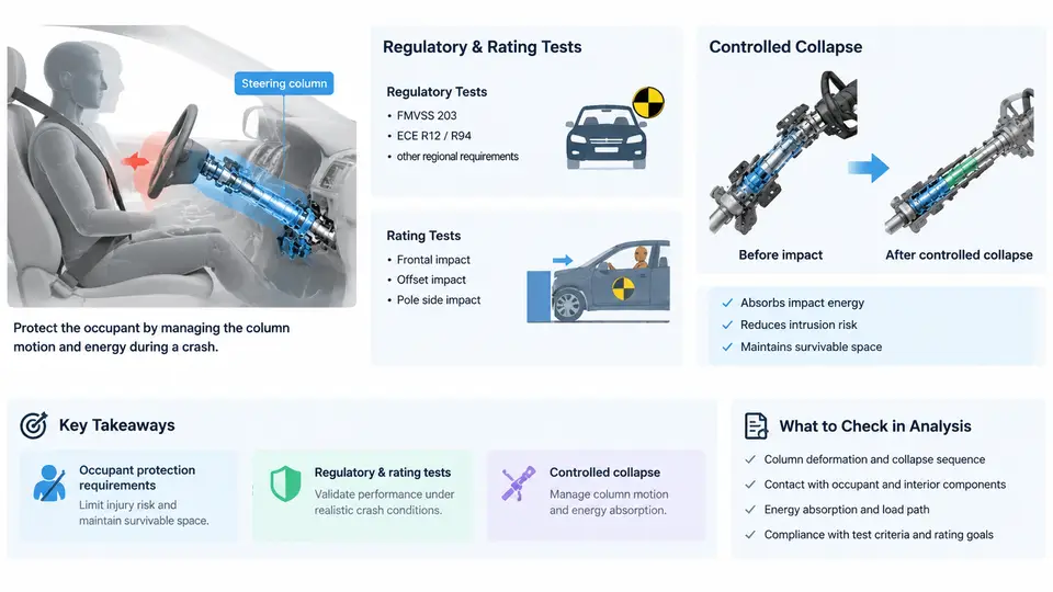
The steering column is the primary structural and control interface between the driver and the vehicle. In a frontal crash, it is also one of the few components that can directly injure the occupant it is meant to serve. A rigid column that transmits the full deceleration of the body structure into the steering wheel will drive the wheel and shaft rearward into the driver's chest and head. Modern steering column design therefore treats the column as a controlled energy-absorbing element: it must remain stiff enough for precise steering feel and stable column-mounted controls, yet collapse in a predictable, repeatable way when the driver loads it during a crash.
This chapter establishes the physical and regulatory foundation for everything that follows: what the occupant protection requirements actually demand, how regulatory and consumer rating tests differ, and why controlled collapse — rather than simple rigidity or simple weakness — is the governing design principle.
1.1 The injury mechanisms the column must address
Three load paths dominate steering-column-related injury in frontal impact:
- Rearward column intrusion. As the front structure crushes, the steering column can be pushed rearward into the occupant compartment. The driver then contacts the wheel earlier and with higher relative velocity.
- Chest compression against the wheel rim and hub. The steering wheel concentrates load over a small area of the thorax. Excessive chest deflection is the dominant injury mechanism for the column in belted frontal crashes.
- Head and face impact. In higher-severity or unbelted cases, the head strikes the wheel rim or hub, producing head injury criterion (HIC) and facial fracture risk.
The column's job is to reduce the relative velocity and peak force delivered to the occupant by allowing controlled axial stroke. Energy absorbed by column collapse is energy not delivered to the chest.
1.2 Regulatory requirements: FMVSS 208 and ECE R94
In the United States, FMVSS 208 (Occupant Crash Protection) is the governing regulation. For the driver position it specifies a 50th-percentile male Hybrid III dummy in a 56 km/h (35 mph) full-frontal rigid barrier test, belted, with the steering column in its design position. Key evaluation criteria include:
| Parameter | Typical limit | Measurement |
|---|---|---|
| Head Injury Criterion (HIC15) | ≤ 700 | Head CG accelerometer |
| Chest deflection | ≤ 63 mm | Chest potentiometer / IR-TRACC |
| Femur axial force | ≤ 10 kN per leg | Femur load cell |
| Neck injury (Nij) | ≤ 1.0 | Upper neck load cell |
FMVSS 208 also includes an unbelted test condition, which is often the sizing case for column collapse force because the column must absorb occupant energy without belt load sharing.
In Europe, ECE R94 (and the equivalent UN Regulation No. 94) applies a 40% offset deformable barrier (ODB) test at 56 km/h, plus a full-width rigid barrier test at 50 km/h. The offset test produces asymmetric loading and significant column intrusion, making it a demanding case for column stroke and wheel attitude control.
1.3 Consumer rating tests: Euro NCAP and US NCAP
Consumer rating programs push beyond minimum regulatory compliance. Euro NCAP frontal offset tests (50 km/h ODB, and the mobile progressive deformable barrier, MPDB) score chest and head criteria with stricter thresholds and add a "bottoming out" assessment — if the column reaches full stroke and becomes rigid, the score drops sharply. US NCAP uses a 56 km/h full-frontal rigid barrier with a 50th-percentile male dummy and reports a star rating based on combined injury probability.
The practical consequence: a column that just passes FMVSS 208 may still score poorly in Euro NCAP if its collapse force is too high or its stroke too short. Rating programs effectively reward low, stable collapse force with adequate stroke.
1.4 Why controlled collapse, not rigidity or weakness
Two naive designs fail:
- Fully rigid column: transmits peak force directly to the chest; chest deflection and HIC exceed limits.
- Too-weak column: collapses during normal driving (steering feel loss, column shake), or bottoms out early and then behaves rigidly, producing a force spike.
The correct behavior is a force–displacement plateau: the column resists steering loads up to a threshold (typically 2–4 kN at the wheel for normal operation), then collapses at a controlled force (often 3–8 kN depending on the load case and belt configuration) over a defined stroke (typically 80–150 mm). The plateau must be stable — not a spike-then-drop — so the occupant decelerates smoothly.
1.5 The collapse mechanism in practice
Most production columns achieve controlled collapse through one or more of the following:
- Sliding jacket with friction/plastic deformation. An inner tube slides inside an outer jacket; energy is absorbed by friction or by plastically deforming a metal strip.
- Breakaway brackets. The column mounting brackets shear or bend at a calibrated load, allowing the column to translate forward.
- Deformable steering shaft. A collapsible intermediate shaft (e.g., a mesh or splined slip joint) shortens axially.
- Energy-absorbing strap or wire. A metal strap is drawn through a die, converting kinetic energy into plastic work.
The force plateau is set by the combination of these elements. In LS-DYNA, this is typically modeled with *MAT_PLASTIC_KINEMATIC or *MAT_024 for the deforming metal, plus *CONTACT_AUTOMATIC_SURFACE_TO_SURFACE for the sliding interfaces, and *CONSTRAINED_EXTRA_NODES or a joint element for the breakaway bracket. The strain-rate sensitivity (C and P parameters in Cowper–Symonds form) matters because collapse occurs at high strain rate.
1.6 How the column interacts with the restraint system
The column does not act alone. Its collapse force must be tuned together with the airbag and seat belt:
- Airbag: The driver airbag provides a compliant surface that spreads chest and head load. If the column collapses too easily, the wheel moves rearward faster than the airbag can deploy, and the occupant may "bottom out" the airbag.
- Seat belt: The belt limits occupant forward excursion. A belt with a load limiter allows controlled forward motion, which increases column stroke usage. The column force and belt force must be balanced so the chest decelerates smoothly.
- Seat and knee bolster: These control pelvis and lower-extremity motion, which in turn affects how the chest loads the wheel.
A useful rule of thumb: the column collapse force should be low enough that the chest does not exceed its deflection limit, but high enough that the column does not bottom out before the occupant's forward motion is arrested. In practice this is found by iterating LS-DYNA full-vehicle or sled models against the target load case.
1.7 What to take into this course
Every later chapter builds on three ideas from this one:
- The column is a tuned energy absorber, not a rigid structure. Its force–displacement plateau is a design variable.
- Regulatory and rating tests define the load cases and limits. FMVSS 208, ECE R94, Euro NCAP, and US NCAP each stress the column differently.
- Controlled collapse must be validated in LS-DYNA with the right material, contact, and strain-rate models. A plateau that looks right in a plot but is not physically calibrated will mislead occupant injury predictions.
With this foundation, the next chapters move into the detailed mechanics of collapse elements, the LS-DYNA modeling techniques for each, and the validation workflow that connects simulation to physical test.