4. BioRID and Hybrid III dummy positioning
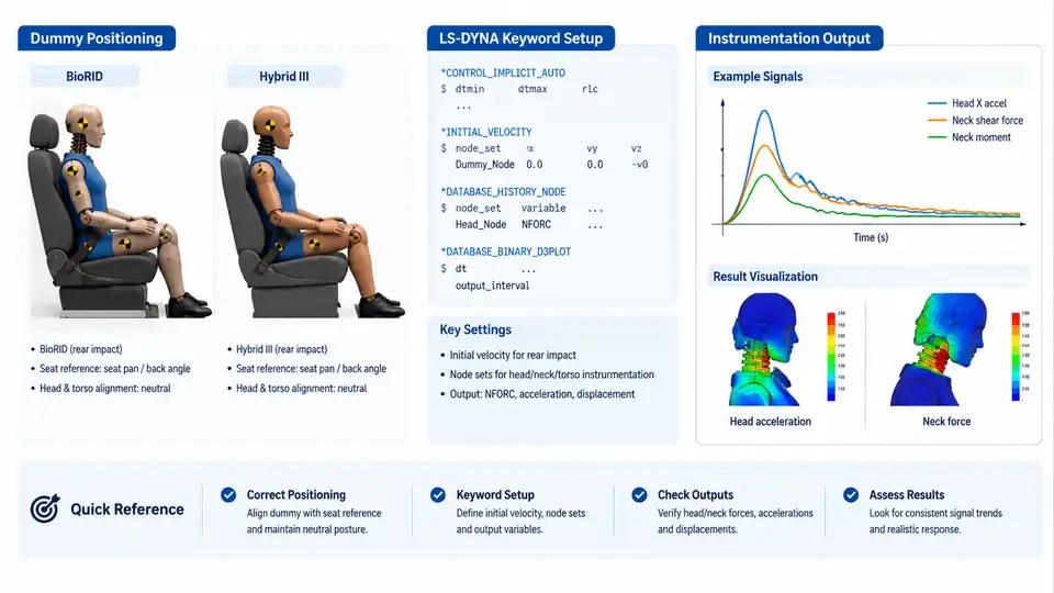
Rear-impact and whiplash simulations are only as credible as the seated posture they start from. A BioRID II or Hybrid III model that is geometrically correct but positioned with the wrong H-point, torso recline, or head-to-headrest gap will produce a neck injury response that no physical sled test can reproduce. This chapter covers the practical mechanics of positioning both dummy types in LS-DYNA: which keywords control posture, how to establish a stable initial condition before the pulse is applied, and how to extract the instrumentation channels that regulators and OEMs actually report.
Why the Two Dummies Demand Different Positioning Logic
Hybrid III was designed for frontal impact, with a stiff lumbar spine and a rigid thoracic cage. BioRID II was purpose-built for rear impact: it has a segmented, flexible spine with realistic curvature, a deformable chest, and a neck that reproduces the S-shaped whiplash kinematics. Consequently, the same nominal seatback angle produces very different spine curvature in the two models. Hybrid III tends to sit "proud" of the seatback, while BioRID settles into it. If you copy a Hybrid III positioning deck directly onto a BioRID model, the BioRID will typically start with an over-curved thoracic spine and a head that is too far from the headrest.
The practical rule: position each dummy against its own target posture, then verify with the same measurement channels. Never assume a shared setup file is valid for both.
Keyword Structure for Dummy Positioning
Positioning in LS-DYNA is not a single keyword. It is a small stack of cards that together define where the dummy sits, how it contacts the seat, and what state it carries into the pulse. The essential set is:
*INITIAL_VELOCITY— sets the sled and dummy pre-impact velocity (usually zero relative to the sled, with the pulse applied later).*INITIAL_VELOCITY_GENERATION— used when the whole model must carry a common velocity field.*BOUNDARY_PRESCRIBED_MOTION_RIGID— drives the sled or seat through the acceleration pulse.*CONTACT_AUTOMATIC_SURFACE_TO_SURFACE— dummy-to-seat and dummy-to-headrest contact.*MAT_cards for the dummy flesh and spine — these must not be altered during positioning.*DATABASE_output cards — where instrumentation channels are requested.
A common mistake is to "settle" the dummy by running a short gravity load step and then restarting. This changes the spine curvature and invalidates the posture. The correct approach is to position the dummy analytically or via a dedicated positioning tool, then verify that the model is in equilibrium at t = 0.
Establishing the Initial Condition
The initial condition has three components: geometry, contact, and stress state. Geometry is set by translating and rotating the dummy parts. Contact is established by ensuring the seat foam and dummy surfaces are just touching, not interpenetrating. Stress state is the hardest — the dummy's flesh and spine elements should carry no residual stress from the positioning step.
In practice, the workflow is:
- Import the dummy model and the seat model into a common coordinate system. Define the origin at the seat H-point, with X forward, Y lateral, and Z up. State this convention explicitly in the deck header.
- Translate the dummy so its H-point coincides with the seat H-point. For BioRID, the H-point is defined by the hip joint center; for Hybrid III, by the H-point fixture location.
- Rotate the dummy about the Y-axis to match the target torso recline angle. Typical rear-impact targets are 22–25° for BioRID and 20–23° for Hybrid III, measured from vertical.
- Adjust the headrest to the target backset. A 50–60 mm backset is common for BioRID; Hybrid III often uses 60–80 mm. Record the actual backset in the output.
- Run a 20–50 ms settling step with gravity and a small damping coefficient. Check that the dummy does not drift more than 2 mm and that contact forces are below 50 N.
- If the dummy drifts, adjust the initial gap or add a temporary
*INITIAL_STRESS_SOLIDto preload the foam. Remove the temporary card before the pulse run.
*INITIAL_VELOCITY to "push" the dummy into the seat. This creates a non-physical pre-impact state and will corrupt the neck response. The dummy must be in static equilibrium before the pulse is applied.
Instrumentation Output Channels
Both dummies report through a standard set of channels. The LS-DYNA output is requested via *DATABASE_ASCII_option and *DATABASE_BINARY_D3PLOT. The channels that matter for rear impact are:
| Channel | BioRID II | Hybrid III | Typical LS-DYNA Request |
|---|---|---|---|
| Head acceleration | Tri-axial at head CG | Tri-axial at head CG | *DATABASE_ASCII_ACCELEROMETER |
| Upper neck force/moment | 6-axis load cell | 6-axis load cell | *DATABASE_ASCII_SPRING or *DATABASE_ASCII_NODFOR |
| Lower neck force/moment | 6-axis load cell | 6-axis load cell | Same as above |
| Chest acceleration | Tri-axial at T1 and T8 | Tri-axial at chest CG | *DATABASE_ASCII_ACCELEROMETER |
| Head-to-headrest gap | Derived from head and headrest nodes | Derived from head and headrest nodes | *DATABASE_ASCII_NODOUT |
| Seatback moment | From seat hinge | From seat hinge | *DATABASE_ASCII_SPRING |
For BioRID, the upper and lower neck load cells are the primary injury channels. The NIC (Neck Injury Criterion) is computed from the relative acceleration between the head and T1, and the Nij is computed from the upper neck load cell. For Hybrid III, the primary channels are the head acceleration and the upper neck moment, used to compute HIC and Nij.
Worked Example: Positioning a BioRID II for a 15 km/h Rear Impact
Consider a sled test at 15 km/h with a pulse peaking at 8 g. The seat is a standard production seat with a fixed headrest. The target posture is 24° torso recline, 55 mm backset, and the dummy H-point at the seat H-point.
Step 1: Set the coordinate system. Origin at seat H-point, X forward, Y lateral, Z up. The sled moves in the −X direction during the pulse.
Step 2: Translate the BioRID model so its hip joint center is at (0, 0, 0). Rotate about Y by 24°.
Step 3: Adjust the headrest to 55 mm backset. Measure the gap between the head rear surface and the headrest front surface at the head CG height.
Step 4: Run a 30 ms settling step with gravity. Check that the dummy H-point drift is less than 2 mm and that the maximum contact force is below 50 N. If the drift exceeds 2 mm, reduce the initial gap by 1 mm and repeat.
Step 5: Apply the pulse via *BOUNDARY_PRESCRIBED_MOTION_RIGID on the sled node set. The pulse is defined in a *DEFINE_CURVE with time in ms and acceleration in g.
*DEFINE_CURVE
         1         0       1.0       1.0       0.0       0.0       0.0
       0.0       0.0
       5.0       2.0
      15.0       8.0
      30.0       4.0
      50.0       0.0
*BOUNDARY_PRESCRIBED_MOTION_RIGID
         1         1         0         1         1         0       0.0
Step 6: Request output. Use *DATABASE_ASCII_ACCELEROMETER for head and chest accelerometers, *DATABASE_ASCII_SPRING for the neck load cells, and *DATABASE_ASCII_NODOUT for the head-to-headrest gap. Set the output interval to 0.1 ms for the first 100 ms.
Step 7: Verify the initial condition. At t = 0, the head acceleration should be zero, the neck forces should be at their static preload values (typically less than 20 N), and the head-to-headrest gap should match the target 55 mm. If the gap is off by more than 5 mm, the headrest position or the dummy recline is wrong.
Common Failure Modes and Troubleshooting
- Dummy drifts during settling. Cause: initial interpenetration between the dummy and seat. Fix: increase the initial gap by 1–2 mm and re-run the settling step.
- Neck forces spike at t = 0. Cause: residual stress from the positioning step. Fix: remove any temporary
*INITIAL_STRESScards and re-run the settling step with a longer duration. - Head-to-headrest gap changes during the pulse. Cause: the headrest is too soft or the contact stiffness is too low. Fix: check the headrest foam material card and the contact penalty stiffness.
- BioRID spine curvature is wrong. Cause: the dummy was positioned using Hybrid III targets. Fix: re-position using BioRID-specific targets and verify the spine curvature against the BioRID geometry manual.
Key Takeaways
Positioning is not a cosmetic step. It defines the initial stress state, the contact geometry, and the posture that the neck response is measured against. For BioRID, use BioRID-specific targets; for Hybrid III, use Hybrid III targets. Always run a settling step and verify equilibrium before applying the pulse. Request the instrumentation channels explicitly, and check the t = 0 values against the expected static preload. A positioning error of 5 mm in backset or 2° in recline can shift the NIC by 10–15%, which is often the difference between a passing and failing seat design.