1. Rear impact and whiplash injury mechanis
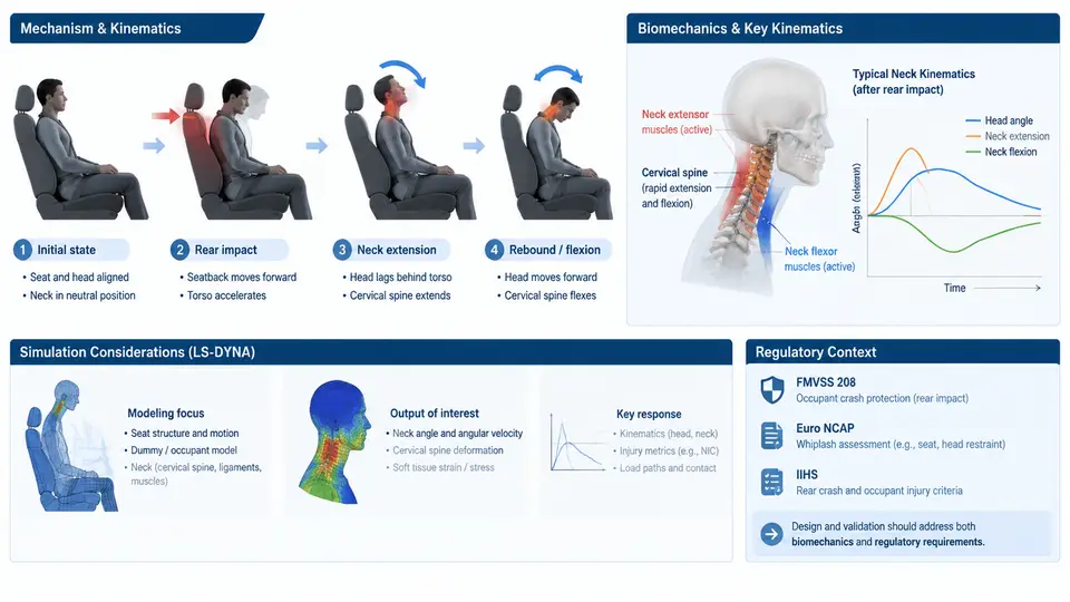
Rear-end collisions are the most frequent crash mode on public roads, and although they often occur at relatively low delta-v, they produce a disproportionate share of long-term neck injuries. For an LS-DYNA analyst, the challenge is not merely reproducing vehicle motion but capturing the coupled response of seat, head restraint, occupant, and cervical spine within the first 150–300 ms. This chapter establishes the biomechanical, kinematic, and regulatory foundation that every subsequent model must respect.
Why Whiplash Is a Kinematic Problem Before It Is a Structural One
Whiplash-associated disorders (WAD) arise from a rapid, non-physiological relative motion between the head and torso. In a rear impact, the struck vehicle is accelerated forward by the bullet vehicle. The occupant's torso is loaded through the seatback, while the head — restrained only by inertia and neck soft tissue — lags behind. This creates a characteristic retraction phase: the cervical spine adopts an S-shaped curve, with lower segments in flexion and upper segments in extension. The S-curve is the critical injury-relevant event, not the peak extension angle that follows.
Three kinematic phases dominate the first 200 ms:
- Retraction (0–60 ms): Torso moves forward with the seat; head remains nearly stationary. Upper cervical extension and lower cervical flexion produce the S-curve. Facet joint compression and capsular strain peak here.
- Extension (60–120 ms): Head rotates rearward relative to the torso. If the head restraint is too low or too far back, the neck hyperextends beyond physiological limits.
- Rebound (120–250 ms): Elastic energy returns the head forward, often producing a secondary flexion wave. This phase is frequently underestimated in simplified models.
The practical consequence for simulation is that a model which only tracks head rotation angle will miss the retraction injury mechanism entirely. LS-DYNA output must include relative intervertebral rotations, facet contact forces, and capsular ligament strain — not just global head kinematics.
Biomechanical Injury Criteria and Their Simulation Counterparts
Regulatory and consumer-test protocols translate the above kinematics into measurable criteria. The most widely used are NIC (Neck Injury Criterion), Nij (normalized neck injury criterion), and the more recent NICmax and LNL (Lower Neck Load) measures. Each maps to specific LS-DYNA output requests.
| Criterion | Physical Basis | LS-DYNA Output | Typical Threshold |
|---|---|---|---|
| NIC | Relative horizontal acceleration between head and T1 | Accelerometers at head CG and T1 | 15 m²/s² (low-speed) |
| Nij | Combined axial force and bending moment at occipital condyle | Cross-section forces in neck elements | 1.0 (normalized) |
| LNL | Lower neck shear and moment | Force/moment at C7–T1 | Depends on protocol |
| Facet force | Contact pressure in zygapophysial joints | Contact force in facet definitions | Injury-specific |
NIC is defined as:
NIC = 0.2 * a_rel * v_rel + v_rel²

where:
  a_rel = relative horizontal acceleration (head CG - T1) [m/s²]
  v_rel = relative horizontal velocity (head CG - T1) [m/s]
  0.2   = characteristic length factor [m]
In LS-DYNA, this is not a built-in card. You must extract head CG and T1 accelerations from *DATABASE_ASCII or d3plot history variables, then post-process. A common mistake is using nodal acceleration without filtering; SAE J211 Class 60 filtering is mandatory before computing NIC, otherwise high-frequency noise inflates the result by 30–50%.
Regulatory and Consumer-Test Context
Three frameworks drive most rear-impact simulation requirements:
- FMVSS 202a (US): Dynamic rear-impact test at 32 km/h delta-v, requiring head restraint geometry and dynamic performance. LS-DYNA models must reproduce seatback rotation and head restraint engagement.
- ECE R17 (Europe): Static and dynamic requirements for seat strength and head restraint height/backset.
- Euro NCAP / IIHS: Consumer tests using sled pulses (e.g., 16 km/h and 24 km/h) with BioRID II ATD. These are the de facto targets for whiplash simulation because they demand NIC and Nij compliance.
The BioRID II dummy is the standard occupant surrogate. Its cervical spine has 24 vertebrae-equivalent segments with calibrated stiffness and damping. When building an LS-DYNA model, the dummy must be positioned with the same backset and seatback angle as the physical test — typically 10–20 mm backset and 25° seatback. A 5 mm backset error can shift NIC by 2–3 m²/s².
From Mechanism to Model: What the Analyst Must Capture
The figure below summarizes the causal chain from vehicle pulse to injury metric, and identifies the LS-DYNA modeling elements that correspond to each stage.
Practical Setup: A Minimal Reproducible Sled Model
To make the above concrete, consider a baseline LS-DYNA sled model for a 24 km/h rear impact. The following inputs are representative and intended as a starting point, not as validated test data.
*BOUNDARY_PRESCRIBED_MOTION_RIGID
$#  nsid       dof       vad      lcid        sf        vid
         1         1         0         100       1.0         0
$# lcid = 100: sled acceleration pulse, 0 to 24 km/h over 80 ms

*DATABASE_ASCII
$#    dt    binary      lcur       ioopt
  1.0E-4         0       200         1
$# lcur = 200: head CG and T1 accelerometers

*DATABASE_HISTORY_NODE
$#   id1       id2       id3       id4
   5001      5002         0         0
$# 5001 = head CG node, 5002 = T1 node
After the run, extract the two acceleration histories, apply SAE J211 Class 60 filtering, and compute NIC. A correct model should show NIC peaking between 40 and 70 ms, coinciding with the retraction phase. If NIC peaks after 100 ms, the seatback is likely too stiff or the head restraint backset is too large.
*CONTACT_AUTOMATIC_SURFACE_TO_SURFACE is defined between the head and head restraint, and that the dummy is not initially penetrating the seatback.
What This Means for the Rest of the Course
Every subsequent chapter builds on three requirements established here. First, the model must resolve the retraction phase, which means adequate mesh density in the cervical spine and correct seatback compliance. Second, injury metrics must be computed from filtered, physically meaningful outputs — not raw nodal values. Third, the regulatory pulse and dummy positioning must be documented and reproducible, because a 5 mm backset change or a 2° seatback angle change can alter NIC by more than 10%. With this foundation, the next steps — seat and head restraint modeling, BioRID II positioning, and pulse validation — become engineering tasks with clear acceptance criteria rather than blind simulation runs.